
Corrosion Monitoring and Light Weight Deflectometers
To support corrosion investigation works one of our articles this month talks about tools for corrosion monitoring. We also discuss the benefits of Light Weight Deflectometers in evaluating pavement systems.
Light Weight Deflectometer vs. Nuclear Density
Whilst design and quality control measures for pavement construction vary across Australia, there are a lot of similarities in approach by the different state agencies in charge of road construction. The most prevalent method for design employs a mechanistic design approach that uses lab California Bearing Ratio (CBR) tests for strength of the base courses. During construction Nuclear Density Gauges (NDG) are used for the majority of quality control in regards to the level of compaction achieved and whether it meets the standards specified in the design.
Interestingly overseas the design approach has changed over time from a traditional empirical approach to a hybrid mechanistic approach. In the traditional approach the base, subbase and surface layer type and thicknesses were based on their strength, often measured using the CBR method. However flexible pavements seldom fail owing to subgrade strength failures during their service life (Huang 1993). In many jurisdictions the method has change to a mechanistic approach based upon resilient modulus. This is because most failures were due to excessive rutting and cracking of the pavement layer as a result of fatigue, temperature changes or softening caused by the surface layer cracking (AJ Puppala 2008).
One of the advantages of the hybrid mechanistic approach is that the elastic modulus can be back-calculated from non-destructive field testing using the Light Weight Deflectometer (LWD). Hence the main design characteristic of Resilient Modulus can be determined in the field and used as a construction quality control measure. Tying the factors used in design to properties measurable in the field better than the unrelated CBR and Nuclear Density Gauge method used in Australia. There are also other factors that make the LWD a more attractive alternative to NDG when examined in a practical sense.
Theory
LWD
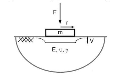 A LWD measures the deflection caused when a dropped weight applies force to a bearing plate placed upon soil and pavement systems. Embedded load cell measures actual impact force to calculate stiffness (peak force ÷ peak displacement) and modulus based on soil type (granular, clay or mixed).
The calculation of Young’s Modulus relies upon solving for a load applied through a rigid circular plate onto an elastic material.
In practice the LWD’s software is used to calculate stiffness and modulus from three sample drops taken after the machine is correctly seated in the test position.
NDG
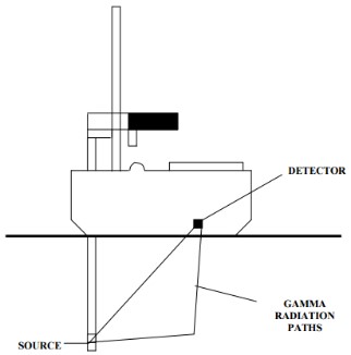 On the other hand, the NDG makes use of a source of gamma radiation for density measurement and a source of neutron radiation for moisture measurement. The gauges emit a cloud of particles and the detectors built in the gauges count the received gamma particles (scattering and absorption) and slow neutron radiation which is a function of the hydrogen content of the material being tested.
Those counts can be further converted to material density or moisture content level by electronics in a calibrated nuclear gauges. For the density measurement, there are two test mode available- direct transmission and backscatter mode. In practise the direct transmission method is the only accepted by many agencies.
 During direct Transmission the nuclear gauge is placed on the material surface with gamma radiation source in a rod lowered into the material. Then the radiation source passes through the material to be received by the detector. The counts obtained provide a measure of the average density of the material between the source and the detector.
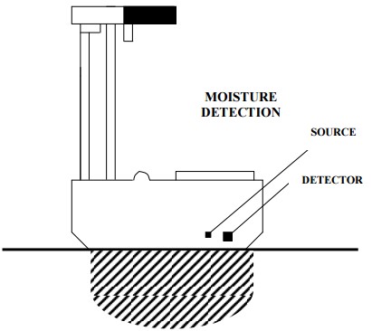
Moisture content measurement can only be carried out in the backscatter mode with the neutron radiation source and the detector close together (all inside of nuclear gauges) to formulate the linear relationship between moisture content in material and captured radiation.
Comparison of LWD vs NDG
As well as the technical comparison raised in the introduction regarding stiffness or modulus as a quality control method there are also practical aspects that mean that NDGs have a number of issues. These include strict regulation in usage, safety burdens, expensive in logistics and maintenance etc.
Usage
NDG contain a radiation source which is potentially harmful for human body, the time an operator can be exposed to radiation is constrained. On top of that, keeping a safe distance and possible shielding are also recommended. Licencing is a critical part of operating nuclear gauges as one needs to be properly trained and understand the potential damage it might cause to health. Compare this with the LWD which is a quick and easy on-site test, that can be performed with no special certification with immediate results. A single person can perform the test as the system is portable and lightweight (less than 30 kg in total unit weight generally).
Calibration
Operating an NDG requires regular calibration of the device to ensure the correct conversion of count ratios to density or moisture measurement values. Human error, the effects of surrounding environment, mishandle during shipping and moisture content in the gauges can all lead to inaccurate readings. On the other hand, an LWD is constructed of durable stainless steel with a simple design that makes use of an embedded spring assembly inside a falling weight. The sensors include a geophone and load cell to measure the plate deflection and impact force respectively. These sensors are stable and require minimal calibration.
Transportation and Storage
All nuclear gauges must be certified by local authorities as serviceable to operate and licences will need to be issued to company and operators. On top of that, Gauges must be checked regularly to make sure there is no leakage of radiation. The storage and transport procedure of nuclear gauges is strict and expensive. Nuclear gauges must be locked and shuttered in a safe place within a fire-resistant container. During transportation, gauges need to be stored in container and keep it in an unoccupied part of the vehicle, they must be immediately returned to storage after use. There are no such requirements for an LWD.
Accuracy
In a study published by Horhota (2015) it was found that within a certain moisture level and a relatively smooth testing surface, the LWD tested provided comparable test results of NDG in terms of coefficient of variance. Based on the statistical analyses and the experience gained from extensive use of the equipment in US (by the University of Florida and Florida DOT), the LWD, in combination with the Dynamic Cone Penetrometer was selected for in-place soil testing for compaction control acceptance in replacement of the NDG.
The Olson Instruments LWD
The LWD-1 module for the Olson NDE360 is an excellent system recently released in the Australian market. Features that set it apart from the competition are:
- A load cell to measure the actual force applied so as to calculate stiffness
- The ability to mount two external geophones for additional SASW layer modulus determination
- A wheel base that allows single person operation without OHS issues regard the carrying of the device
Bibliography
- Pavement Analysis and Design, Prentice Hall, Inc. (Huang, Y.H., 1993)
- Estimating Stiffness of Subgrade and Unbound Materials for Pavement Design- A Synthesis of Highway Practice, TRB (AJ Puppala 2008)
- Performance-Based Quality Assurance/Quality Control (QA/QC) Acceptance Procedures for In-Place Soil Testing Phase 3 (Horhota 2015)
Corrosion Monitoring Methods
In construction, the most widely used composite material is Steel Reinforced Concrete, which has excellent properties in both compression and tension. For most concrete structures, especially those close to marine environments, the long term durability is controlled by steel because of it sensitivity to corrosion due to chemical ingress. By the time damage is visible (in the form of cracking, rust staining or concrete spalling) corrosion is already advanced and repairs expensive. Corrosion inspection and monitoring tools can determine if corrosion is occurring before visible signs of damage and/or track the ingress of environmental contaminants that accelerate steel corrosion.
Corrosion mechanisms in concrete
The mechanism of corrosion in Concrete is an electrochemical reaction involving the presence of Oxygen, moisture and an electrolye. Like a battery, a transfer of electrons from cathodic regions to that of anodic regions begins. Steel is originally protected by a layer of passive Iron Oxide, which forms at in alkali conditions with high pH levels (12-14 pH).
Chlorides
Chlorides interact with the passive surface layer formed by steel in alkaline concrete. Once Chrloide ions reach a critical concentration at the reinforcing this film will brewak down and allow corrosion in the presence of water and Oxygen.
Carbonation
Carbon Dioxide reacts with water to form weak acid that converts Calcium Hydroxide to Calcium Carbonate, lowering pH and creating an environment where the steel is no longer protected and able to being corroding.
Insitu testing
Carbonation
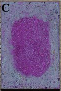 Testing for Carbonation requires a fresh surface fracture, typically a small core is taken and broken with cold chisel to expose fresh concrete for testing with a pH indicator. A solution of Phenolphthalein in Ethanol is a common chemical test used to identify the depth of carbonation, concrete with a pH lower than 10 is considered to be carbonated. When affected by Phenolphthalein the Carbonated section will be colourless, whilst concrete with a higher pH will be stained pink.
Chloride Profile
The Chloride profile is usually measured by processing samples of ground concrete to evaluate chloride in the samples. Either samples can be ground from a core at increasing depth or drilled samples collected on site for increasing depths. The chloride concentrations at the prescribed depth are then recorded after lab testing. The concentration profile describes the diffusion of Cl into the concrete.
NDT Inspection
In relation to the insitu inspection of corrosion in concrete elements, there are several reliable ways of determining this. Destructive inspection involves the breakout of the reinforcement which would visually expose areas of corrosion, this is the only way to determine the remaining cross sectional area of the reinforcing steel in a heavily corroded structure. However this only indicates the condition at one point of the structure.
Non-destructive methods are usually preferable, with each measurement contributing to identifying the scale of latent corrosion. The resistivity of concrete is an important control on the rate which corrosion can progress. Resistivity is measured in kΩcm, consequently the more electrically resistive the concrete, the slower the rate of corrosion.
Half-cell potentials require a connection to the reinforcement to create a circuit. In the test the reference electrode in held on the surface and acts as one half cell, whilst the reinforcing in concrete acts as the other. The potential difference is recorded in a grid pattern over the structure and a contour plot is generated showing the particularly negative (or anodic) regions. Cu/CuSO4 or Ag/AgCl Half Cells are usually used as the reference elctrode. By locating the anodic regions on the structure the likely regions where corrosion could be occurring are located. Note this test does not indicate that corrosion is occurring or anything to do with the rate, rather a probability of corrosion can be interpreted.
Monitoring Instruments
Reference Electrodes
This is similar to the half cell test describe above but instead permanent reference electrodes are retro-fit or built into the concrete for a permanent monitoring point. The two most commonly used for corrosion investigation within structures are Silver / Silver Chloride Electrodes [Ag/AgCl] and manganese dioxide reference electrodes.
Counter Electrodes
Used when measuring corrosion rates using polarization techniques, a counter electrode is used to apply a current into the concrete, which will affect the measured potentials and can be used as part of the calculation of a corrosion rate.
Ladder Probes / Cl Probes
 Ladder probes such as the Corrowatch are used to indirectly measure the diffusion rate of environmental chlorides through the concrete. They consist of a number of steel pellets within the cover region of the concrete at increasing distance from the surface. By monitoring their half cell potential, corrosion currents or rates vs a reference half cell and a counter electrode the probes can be classified as passive or actively corroding.
If the time to corrosion initiation is recorded for two or more pellets the real rate of diffusion can be calculated and used as input back into the structures durability calculation and time to active corrosion of the reinforcing established.
Retrofit
Conventionally Ladder Probes are embedded at the time of construction, but it is now possible to retrofit specially designed systems such as the CorroRisk
Data Logging
Ammeter / Multimeter
The most basic method to record data from corrosion monitoring instrumentation is when collected and recorded by hand using basic electronic measurement tools such as Multimeters or zero ohm resistance ammeters, where there are only a couple of points on a structure this may be suited but it will require physical access to the site at least once a year and preferably more often than that.
Basic tools also cannot record corrosion rate measurements
Data recording system
Systems used for corrosion mapping such as the Corromap can be adapted to take the same measurements from reference instruments, in doing so they add a limited data logging capacity and often the ability to measure corrosion rates.
Alternatively, most Ladder probes can be supplied with a meter specific to their data collection, they produce the most correct data output and speed the collection process as typically an operator only need to connect one multi contact connector and start the meter, the CorroZoa is one example of such a system.
Data logger
Where data is required regularly or access is difficult a data logger system can be used. The Camur is one system suitable to this task, able to collect HCP measurements and LPR measurements from multiple installed probes periodically and make them available for remote access.