
Construction NDT News - September 20
Slab Impulse Response Testing for Tunnel Linings
How it works
A Slab Impulse Response (Slab IR) system is designed to identify subgrade voids below slabs-on-grade less than 600 mm thick, or more generally a lack of supporting material behind concrete less than 600 mm thick.
In addition, the Slab IR test method can be used on other concrete structures to quickly locate areas with delaminations or voids in the concrete if the damage is relatively shallow.
This case study explores general theory and interpreation, but the most common project use in Australia is to determine if tunnel lining segments have been correctly grouted in place during TBM tunneling.
Slab IR can be performed on reinforced and non-reinforced concrete as well as asphalt or asphalt-overlay slabs. Figure 1 shows the testing configuration of a Slab IR system. A hammer with a rubber tip and load cell to measure impact force is one input and a velocity transducer placed next to the impact point is the second. The hammer strike moves the test area, and the velocity transducer records the motion and energy levels.
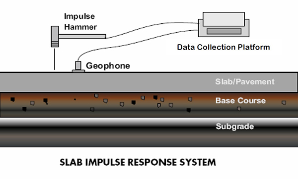 Figure 1– Schematic of Test Set-Up and Apparatus of Slab Impulse Response Test
The output waveforms obtained are converted to the frequency domain as a mobility spectrum, an example is in Figure 2.
Mobility represents the maximum velocity of motion at a given frequency per unit of applied impact force. Essentially high mobility means lots of movement at that frequency of vibration. A high low frequency mobility [0-100 Hz] corresponds to the concrete or pavement moving freely, unsupported by the substrate.
Looking at Figure 2 the mobility between 0 and 100 Hz is low, suggesting this test is over a correclty supported concrete element.
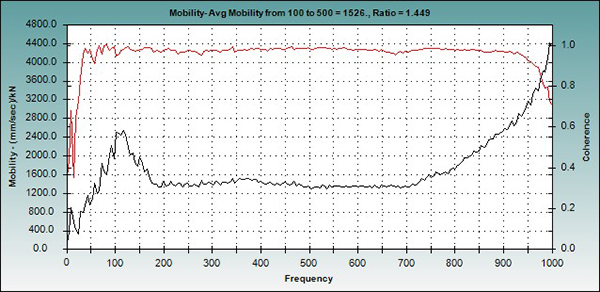
Figure 2 – Mobility is the black line, the red line is Coherence, a measure of data quality.
The most common interpretation procedure is to calculate the ratio between the Peak Mobility value between 1-100 Hz and average [Mean] Mobility value between 100-800 Hz using the procedure given in standard ASTM C1740.
Figure 3 shows two results, one with a ratio of 2.8 and another with a ratio of 7.6, a higher ratio corresponds to a region with lack of support. Results are then commonly confirmed with drilling in a portion of test areas.
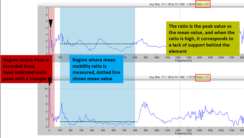
Figure 3 – Interpretation Notes, Peak to Mean Mobility Ratio
UPE Phase Detection Interpretation for QA of Grouting in Precast Walls
The video below looks at Phase Detection / Phase Analysis of Ultrasonic Pulse Echo data, to evaluate the difference between grouted vs unfilled grouting ducts in precast wall panels, constructed to AS 3850.2. It is an expansion on our previous text article from last year on evaluating voiding with many sonic and seismic techniques.
Data was collected with Proceq's PD8000 UPE array, and processed with Pundit Vision Software.