Phone: 02 9453 9999 or Email: sales-operations@pcte.com.au

Impact echo is a sonic/seismic technique used to detect voids and defects and to measure the thickness of concrete plate elements such as walls, floors, tunnel linings and bridge decks.
Impact echo hardware will include a sensor that is pressed against the concrete surface to record sound energy and a manual or automatic impact device to strike the surface.
Software is used to process the raw sound signal and to provide data logging and record keeping functionality.
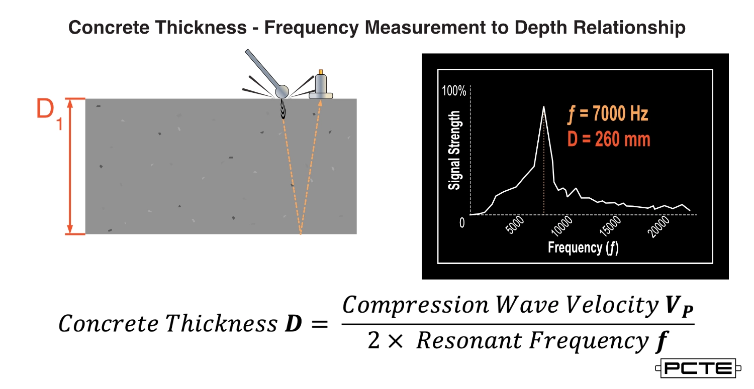
Impact echo measures the resonant response of concrete to an impact, such as a tap with a hammer or specialised Impactor.
Operators record the reflected sound from this impact and use a mathematical process to produce a diagram that shows the signal strength of every sound frequency introduced.
In undamaged concrete the strongest frequency after filtering is the resonant frequency and with an estimate or measurement of sound velocity the thickness of the concrete may be calculated.
Changes to this resonant frequency in other concrete regions will indicate either change in thickness, or locations where voiding and damage are located. Voiding and damage may also be detected by evidence such as multiple strong signals in the frequency diagram or a messy hard to interpret frequency diagram.
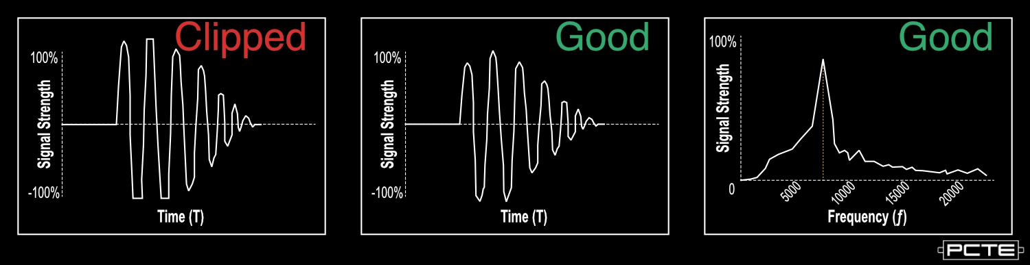
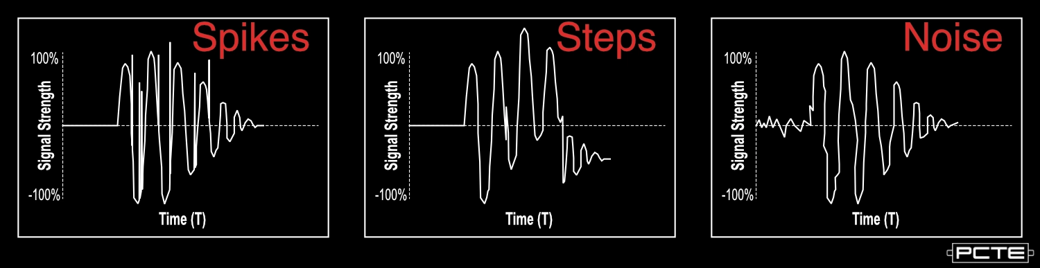
The time domain diagram is the same view as a sound recording program will show a user. Time domain data's primary purpose for an Impact Echo operator is to visually confirm that a test was done correctly and should be saved and interpreted.
Operators look for three details on a time domain diagram;
For interpretation the dominant frequency of a typical area is compared to other nearby regions, a change in frequency or a complex / multiple resonant response indicates a regions requiring further investigation.
To calculate concrete depth the user needs to measure the resonant frequency and estimate or measure a speed of sound.
If the operator is guessing precision the measurement may be as low as a 20% uncertainty, but with physical measurement and calibration the precision can be improved to within 2%.
Voiding and cracking in concrete near to an Impact Echo test location will impact the results, shifting the dominant frequency or introducing additional resonances.
Testing a region to compare voided to un-voided results is the most common technique, typically using data logging functions to create a line or grid of data over a similar concrete geometry. The user may then interpret unexpected changes in the result as a regions of potential defect.
Post tension duct testing also requires a user to compare "good" ducts with complete grouting to potentially voided ducts.
The regions near the duct will have a resonance that differs from the plane resonance without the duct, the additional air in a duct will produce a frequency shift to a lower frequency for ducts without grout.
%20vector%20logo.svg)


