%20vector%20logo.svg)


Phone: 02 9453 9999 or Email: sales-operations@pcte.com.au

The CorroRisk probe has been developed for corrosion monitoring on existing concrete structures. The retrofit probe design press fits black steel anodes to precise bore holes, along with a reference electrode and noble metal cathode for electrochemical monitoring.
Overview | GX1 vs GX2 | SUE & Utilities | Structures & Pavements | Software & Outputs | Case Studies | Specifications | Support
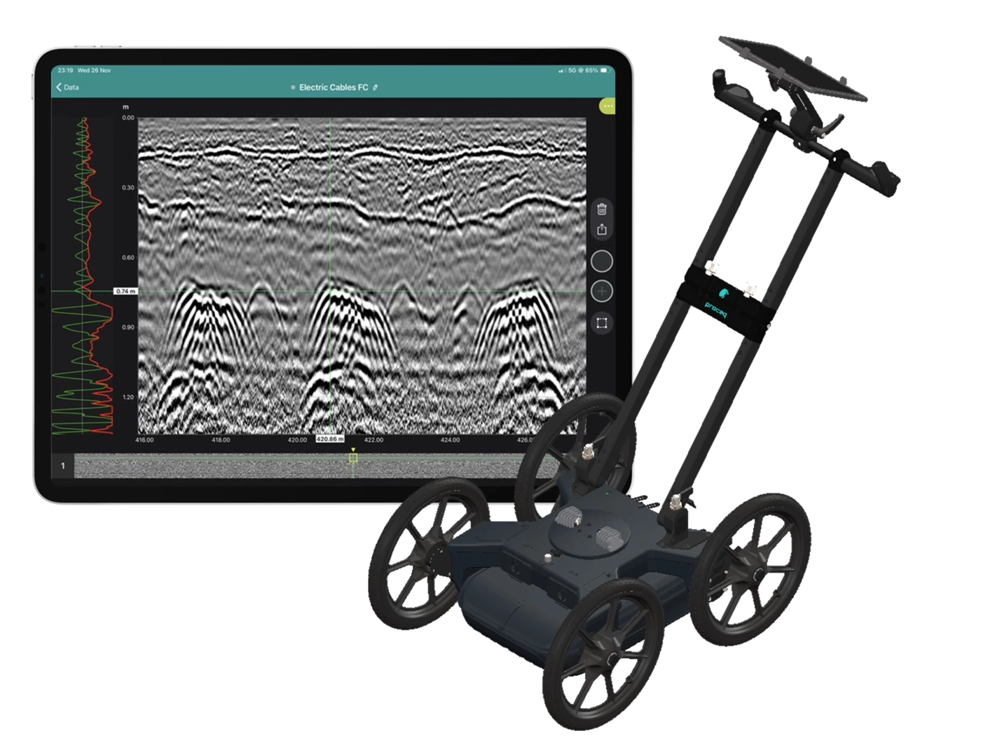
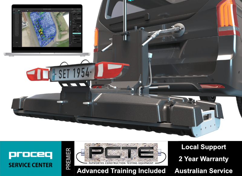
Collect high-density, georeferenced GPR data across wide areas and view the subsurface in 3D as you scan. Choose the GX2 array for SUE and utility mapping, or the GX1 array for structural, bridge and pavement investigations.
Best suited to:
Best suited to:
Recommended array: GX2
Recommended array: GX1
Cover more ground
Collect multiple parallel profiles in one pass instead of uilding a grid line by line.
See results during acquisition
View georeferenced radargrams and time-slice information in the field rather than waiting until the data is returned to the office.
Produce repeatable mapped data
Combine wheel-positioned GPR data with GNSS, project coordinates and survey linework.
Use one platform for two very different applications
Exchange GX1 and GX2 arrays without purchasing two complete cart platforms.
The GX2 transforms the GS9000 into a high-density subsurface utility mapping system. Its 11-channel, low-frequency GPR array captures an 83 cm-wide swath in each pass, helping operators detect and map buried pipes, ducts, cables, voids and other subsurface features. Live georeferenced data lets SUE teams review coverage on site and produce accurate CAD, GIS and project-coordinate deliverables.
1. Plan the survey
Load satellite imagery, CAD information, project coordinates or survey control.
2. Collect dense multichannel data
Survey an approximately 0.82 m-wide swath with 11 channels in each pass.
3. Review data live
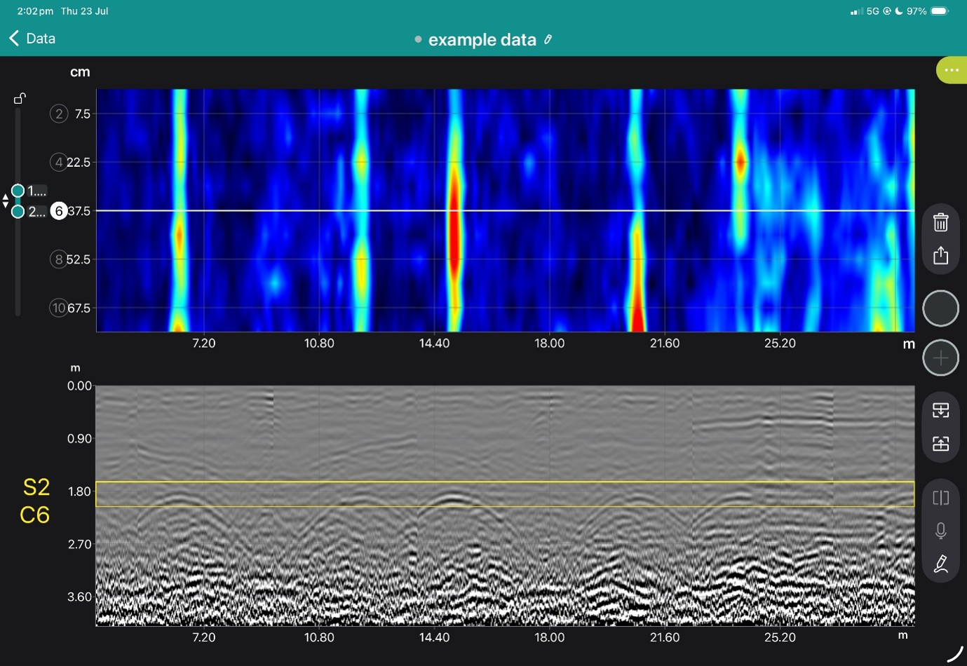
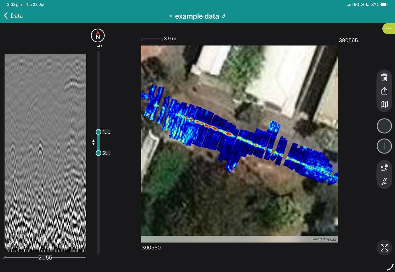
Examine radargrams, georeferenced time slices and marked features while still on site.
4. Interpret and digitise
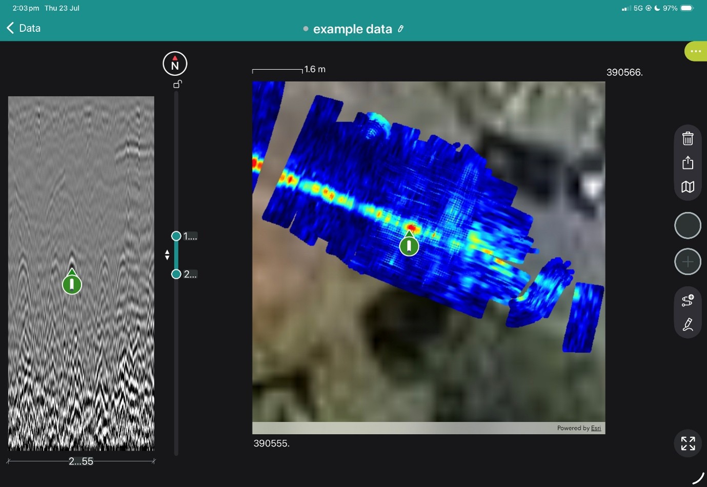
Add points, linework, tags, photographs and field observations.
5. Process and deliver
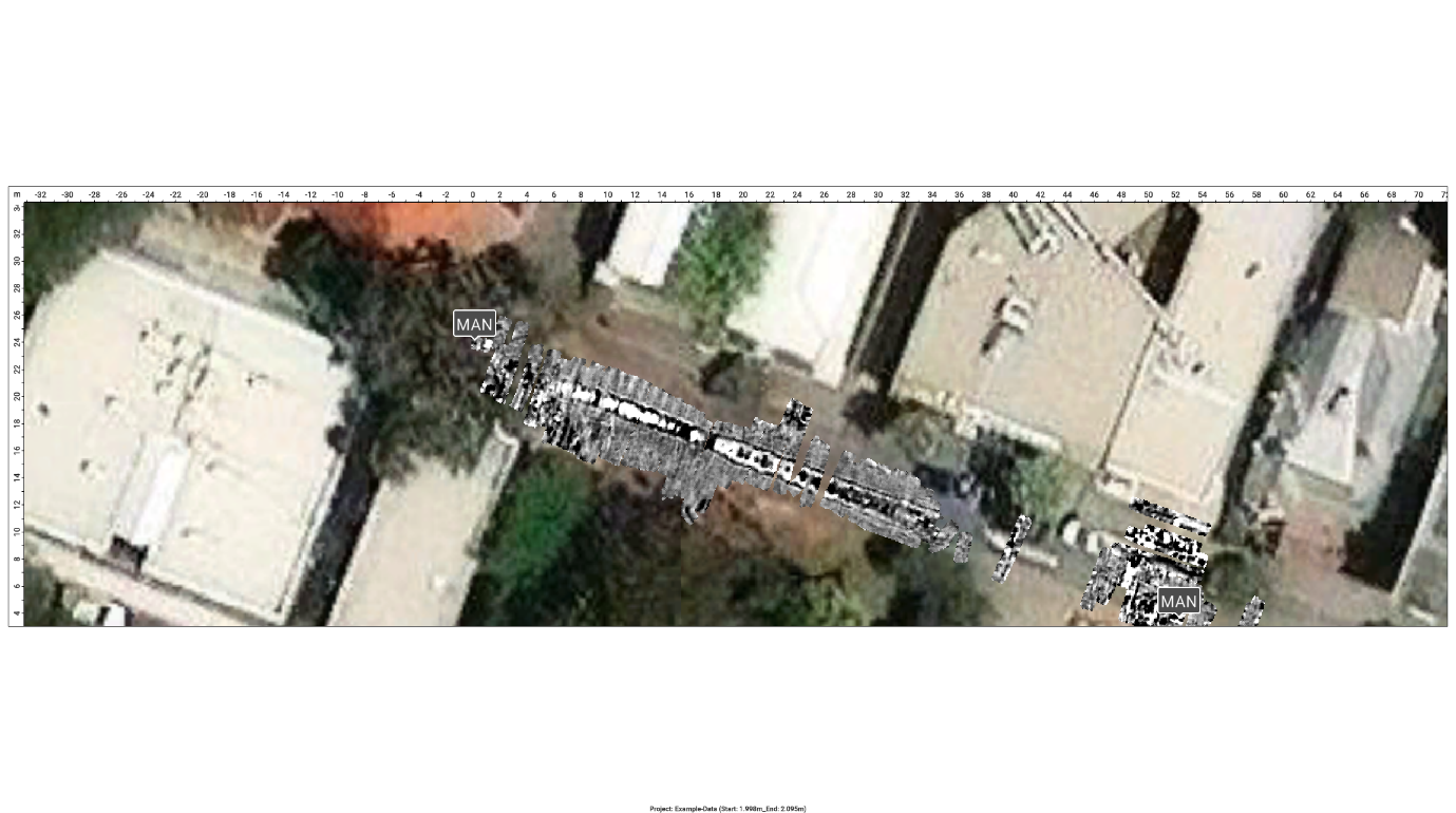
Merge survey areas, apply processing and export mapped information for the customer’s CAD, GIS or reporting workflow.
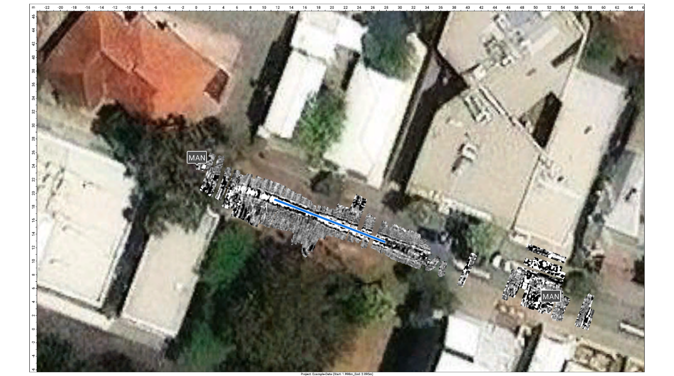
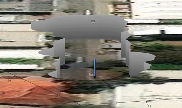
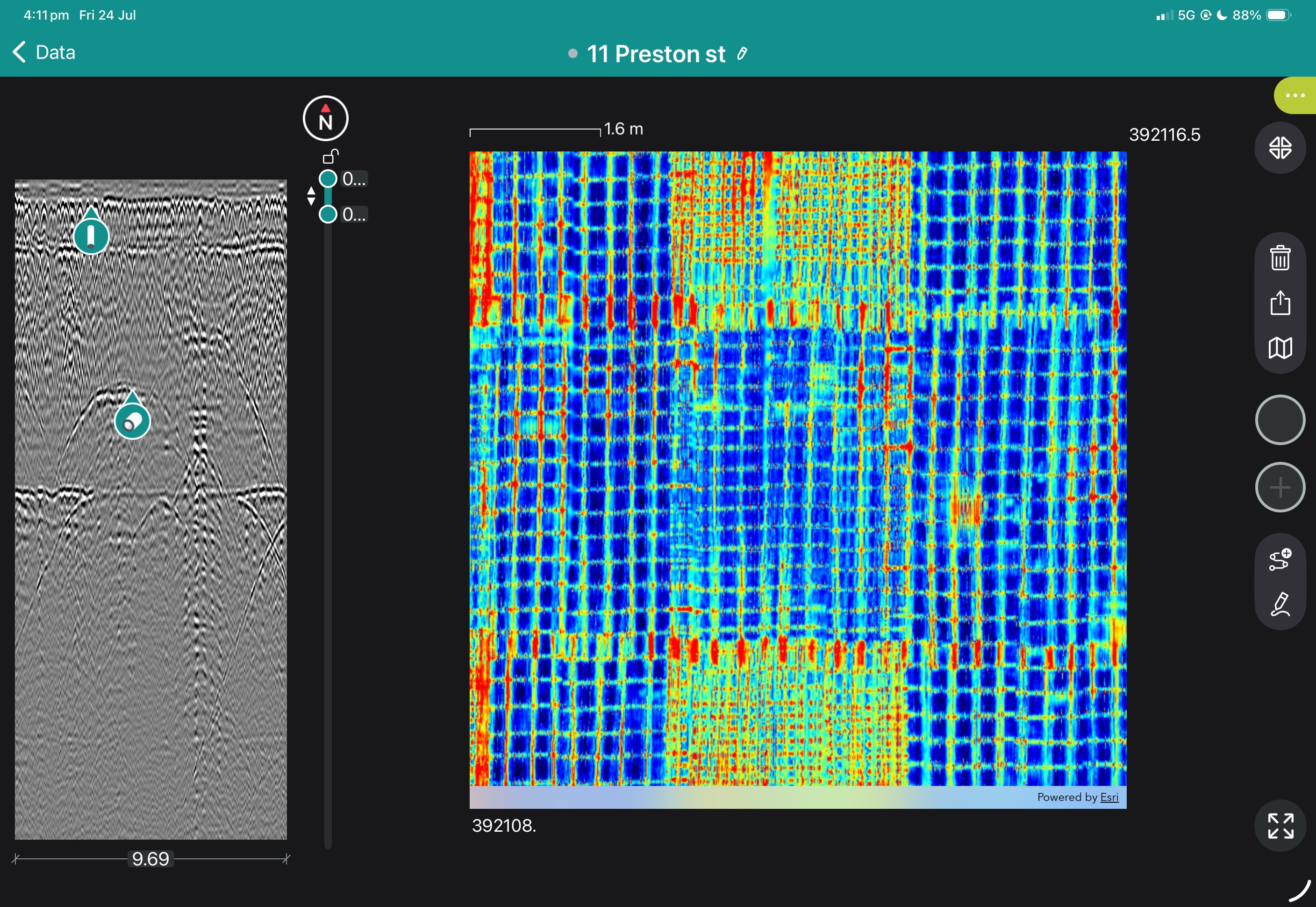
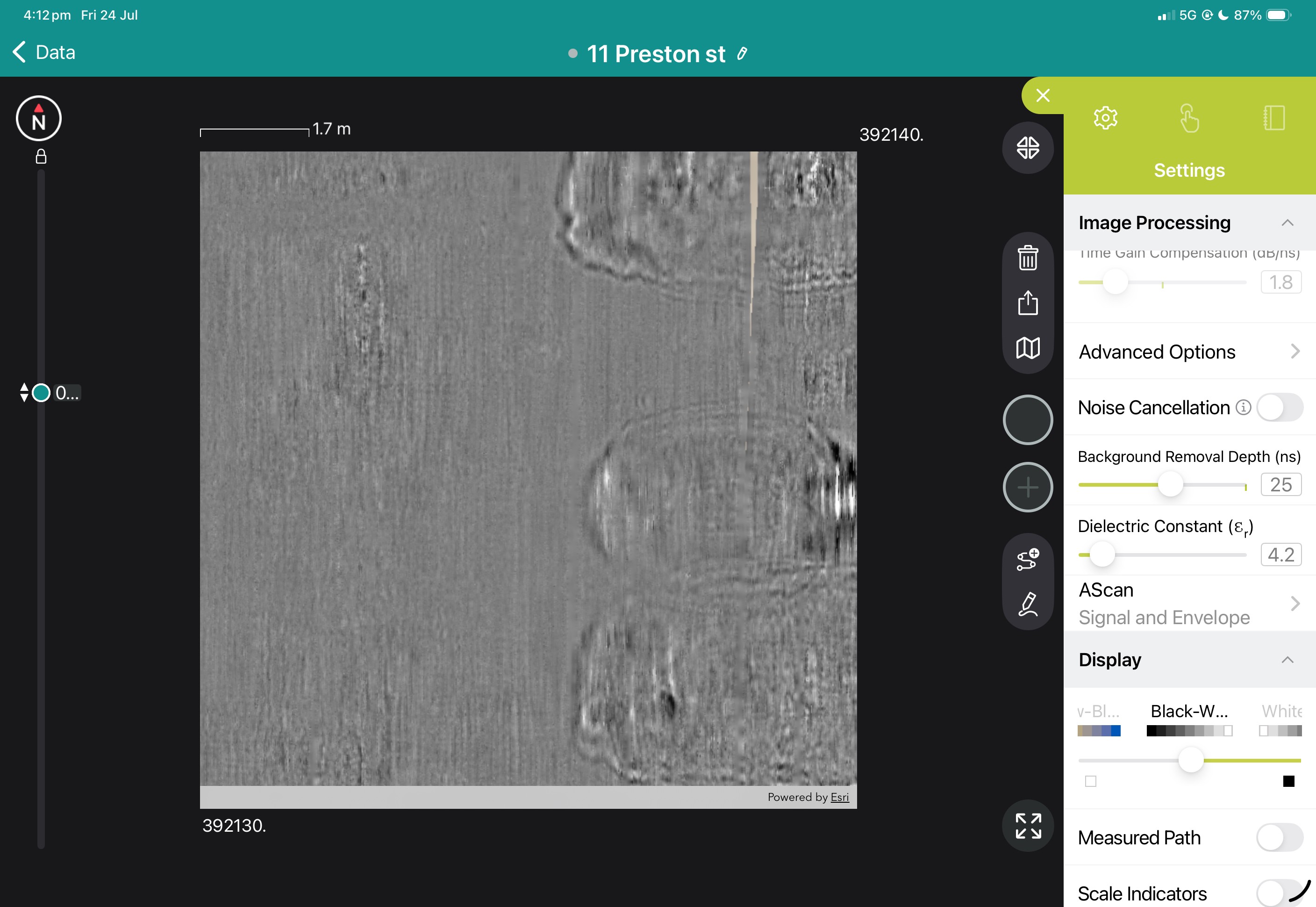
View the images below to see these in action.

The CorroRisk probe is recommended to be used in all types of existing concrete structures, especially in aggressive corrosive environments and where visual inspection is difficult. This could e.g. be pillars in seawater (Figure 1), bridge decks, multi-storey car parks exposed to de-icing salt and various structures in swimming pools.
CorroWatch is recommended for new structures. It is installed before casting the concrete.

The CorroRisk probe consists in the standard version of 4-8 measuring electrodes and 1 combi-electrode. The electrodes are made of the same material as the reinforcement. The combi-electrode consists of a titanium net and a reference electrode (ERE20), which has been developed earlier for use in concrete structures.
Initial corrosion is discovered when threshold values of the potentials or current have been exceeded. The potential of the equilibrium is measured between the combi-electrode and the individual electrodes in the concrete cover.

The CorroRisk is usually mounted in the cover layer between the concrete surface and the outer reinforcement layer. The electrodes are mounted in different but well-defined depths in the cover layer. All electrodes are mounted in a circle around the combi-electrode.
The electrodes are supplied with a coaxial cable, which on the concrete surface is protected by a latticework. The cables are lead to a monitoring box, and e.g. a data logger.

Book a SUE Workflow Demonstration
The GX1 transforms the GS9000 into a high-resolution structural assessment system for concrete slabs, bridge decks and pavements. Its dense, dual-polarisation array captures detailed 3D data across wide areas, supporting reinforcement and cover mapping, moisture and deterioration assessment, and analysis of asphalt and pavement layers. Live visualisation helps confirm survey coverage on site, while post-processing tools produce clear, report-ready condition maps.
1. Define the inspection area
Import the structure, bridge, pavement or survey background.
2. Collect closely spaced profiles
Capture 35 longitudinal and 15 cross-polarised channels with dense spacing.
3. Review coverage in the field
Use live radargrams and time slices to confirm that the required area has been captured.
4. Process the dataset
Apply velocity, gain, background removal, migration, filtering and topographic correction as appropriate.
5. Generate diagnostic maps
Create depth slices, reinforcement maps, layer information or application-specific condition maps.
6. Integrate with the engineering assessment
Export figures, mapped anomalies and raw data for inclusion in the engineer’s final interpretation and report.
Field information
Processed Diagnostic Information
Engineering deliverables
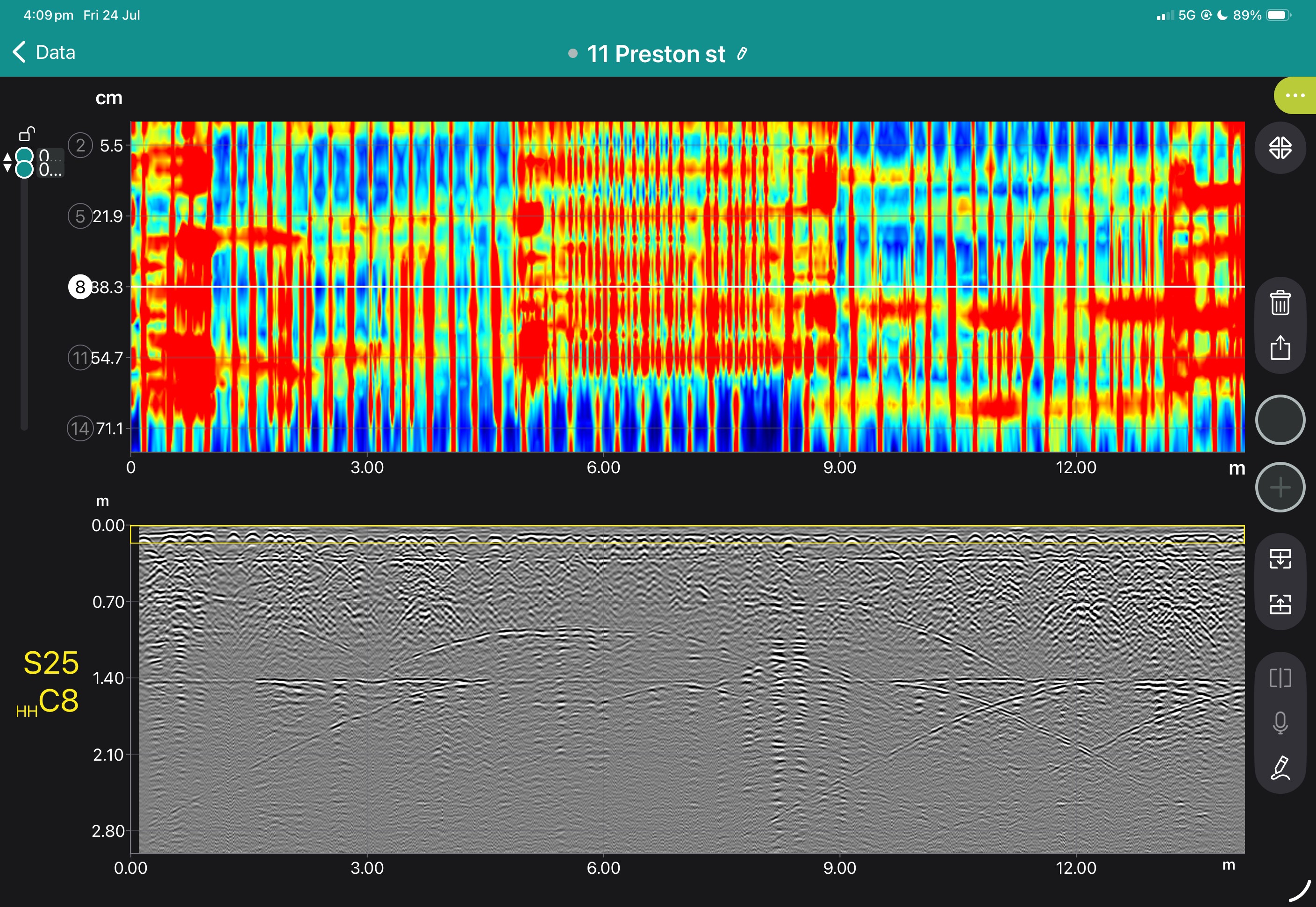
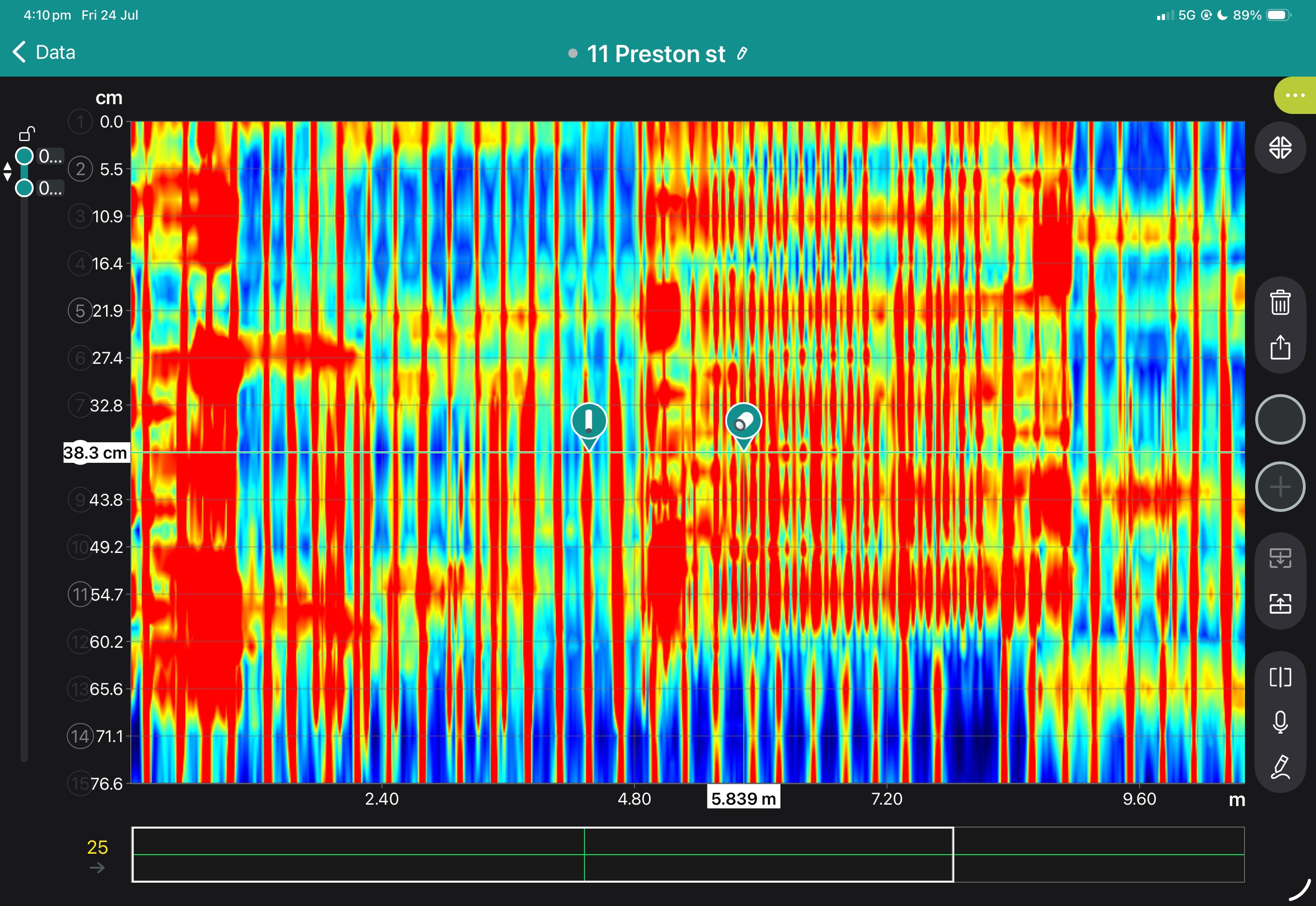
View some of these features at work below, and our case study if you'd like to see more of what the GS9000 can do.




Book a Structural Assessment Demonstration
GS9000 cart with: