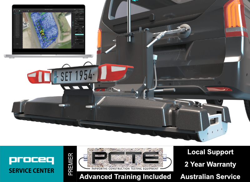
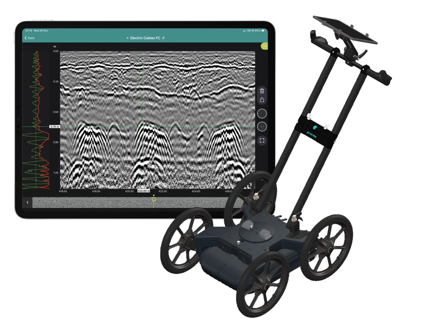
The GM8000 Multi-Channel Ground Penetrating Radar system is a high-performance array-based GPR solution designed for large-area subsurface investigation and infrastructure assessment. Positioned at the upper tier of GPR systems, it is suited to projects where coverage speed, data density and spatial accuracy are critical.
$ 0.00 AUD
This product is out of stock.
Product is not available in this quantity.
Thank you! Your submission has been received!
Oops! Something went wrong while submitting the form.
Collect high-density, georeferenced GPR data across wide areas and view the subsurface in 3D as you scan. Choose the GX2 array for SUE and utility mapping, or the GX1 array for structural, bridge and pavement investigations.
Why use the GS9000 instead of a conventional single-channel GPR?
Cover more ground
Collect multiple parallel profiles in one pass instead of uilding a grid line by line.
See results during acquisition
View georeferenced radargrams and time-slice information in the field rather than waiting until the data is returned to the office.
Produce repeatable mapped data
Combine wheel-positioned GPR data with GNSS, project coordinates and survey linework.
Use one platform for two very different applications
Exchange GX1 and GX2 arrays without purchasing two complete cart platforms.
High-density 3D GPR mapping for SUE and utility investigations
The GX2 transforms the GS9000 into a high-density subsurface utility mapping system. Its 11-channel, low-frequency GPR array captures an 83 cm-wide swath in each pass, helping operators detect and map buried pipes, ducts, cables, voids and other subsurface features. Live georeferenced data lets SUE teams review coverage on site and produce accurate CAD, GIS and project-coordinate deliverables.
Utility corridor mapping
Detection of pipes, ducts and cables
Mapping non-conductive services that may not respond to electromagnetic locating
Congested service investigations
Road-crossing and easement surveys
Potential void and cavity investigation
Pre-excavation and design-stage surveys
Utility mapping to project or local coordinates
The SUE field workflow
1. Plan the survey
Load satellite imagery, CAD information, project coordinates or survey control.
2. Collect dense multichannel data
Survey an approximately 0.82 m-wide swath with 11 channels in each pass.
3. Review data live
Examine radargrams, georeferenced time slices and marked features while still on site.
4. Interpret and digitise
Add points, linework, tags, photographs and field observations.
5. Process and deliver
Merge survey areas, apply processing and export mapped information for the customer’s CAD, GIS or reporting workflow.
SUE Outputs and Deliverables
Georeferenced time-slice maps
Radar profiles
Utility alignments and interpreted linework
Depth estimates
Survey trajectory
Points of interest
Field photographs and annotations
CAD, SHP and KML outputs
SEG-Y raw-data export
Project-coordinate and local-grid outputs
PDF or shareable project reports
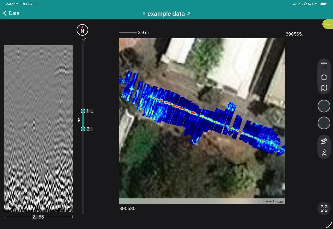
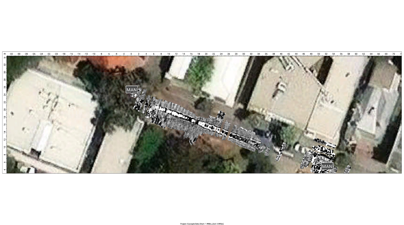
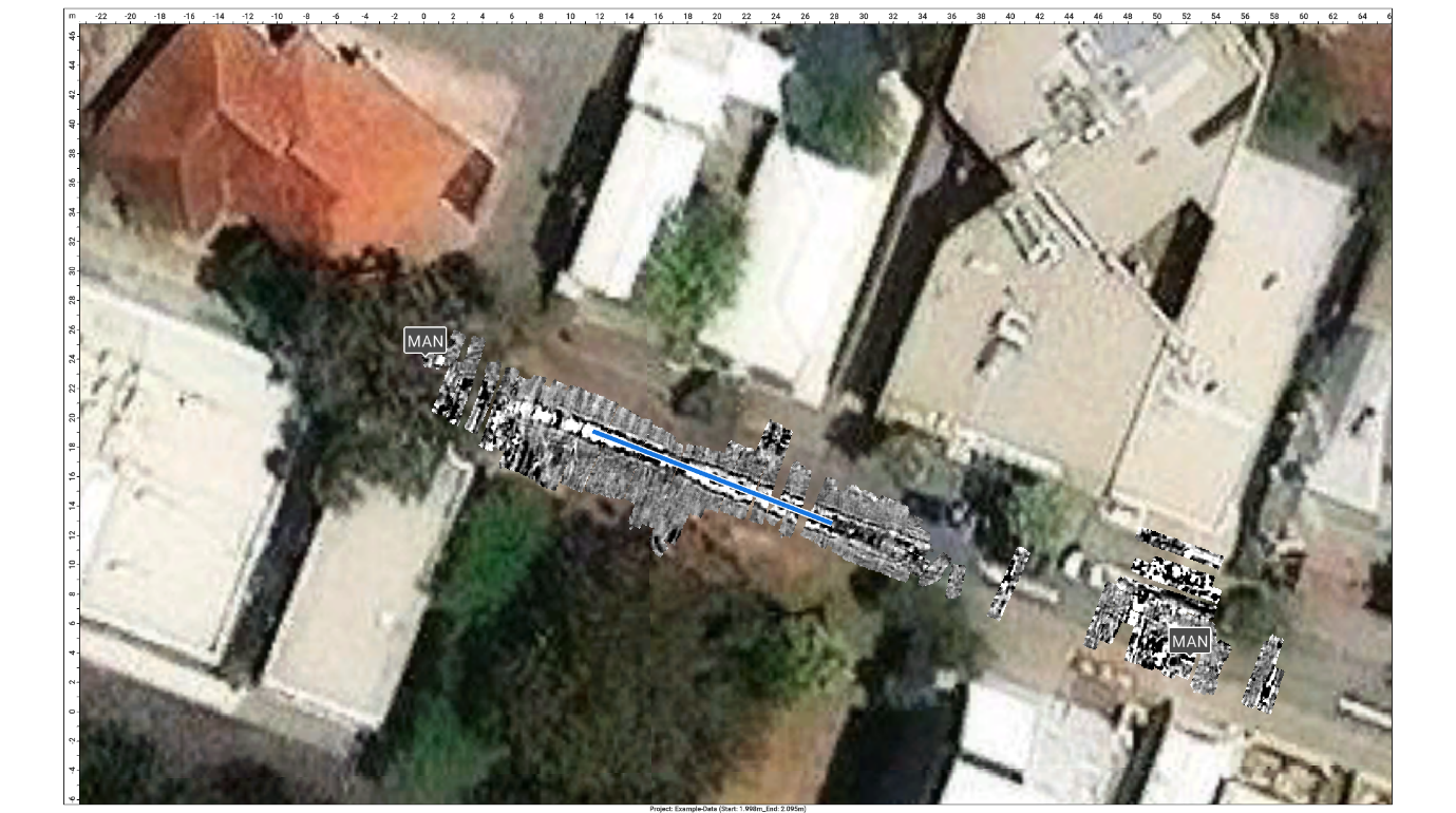
View the images below to see these in action.
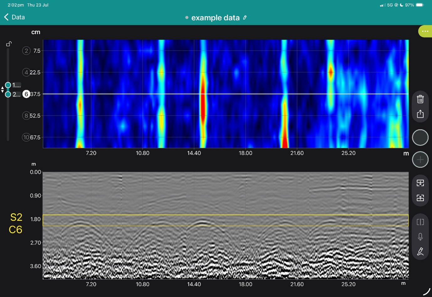
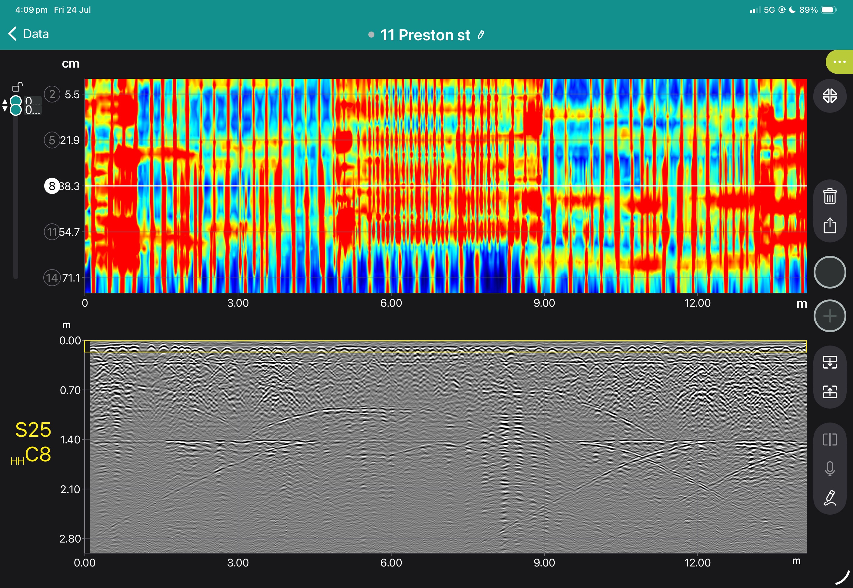
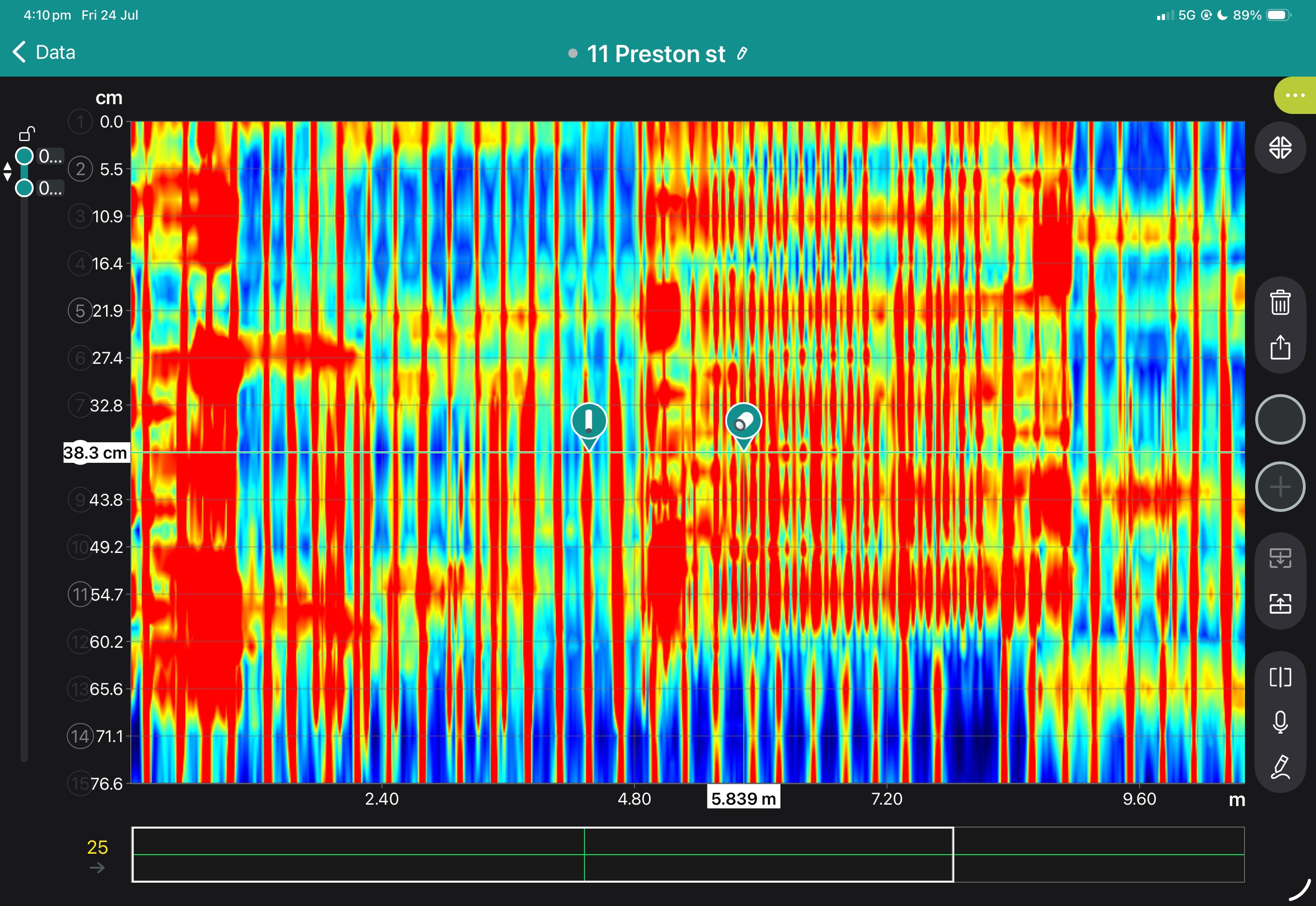
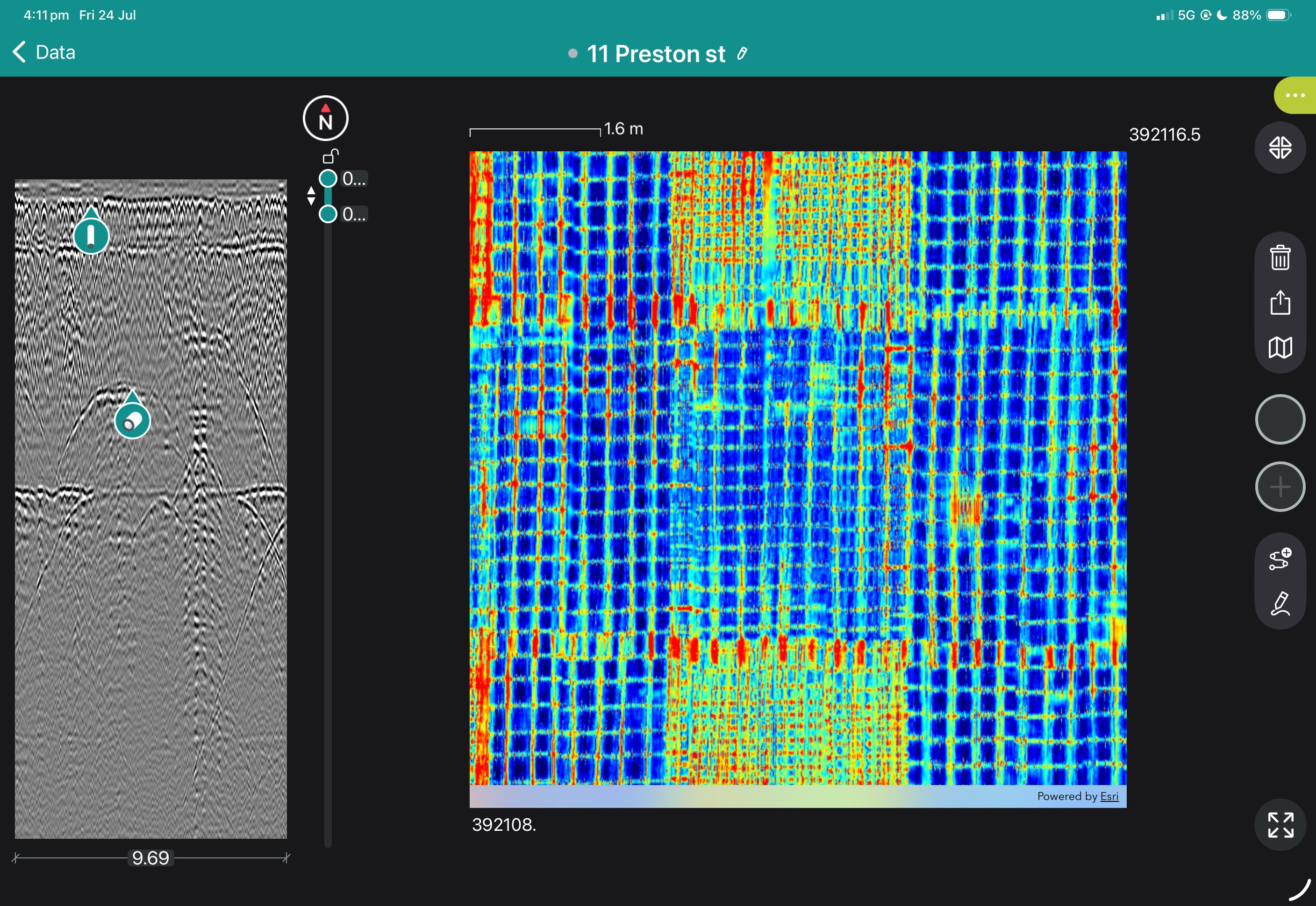
Superline and B Scan from App
Freepath and b-scan from app
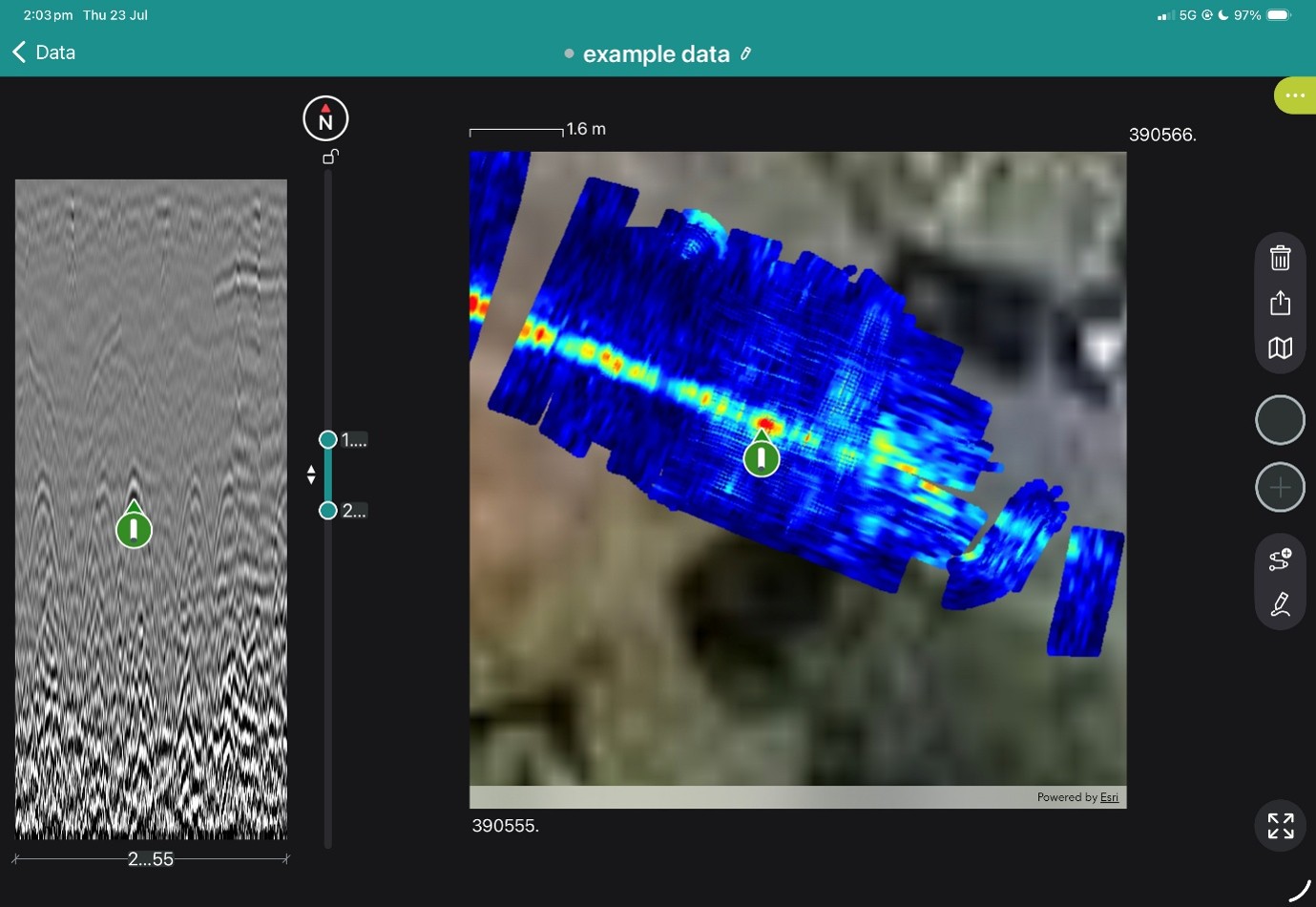
Geolocated tag on freepath in app
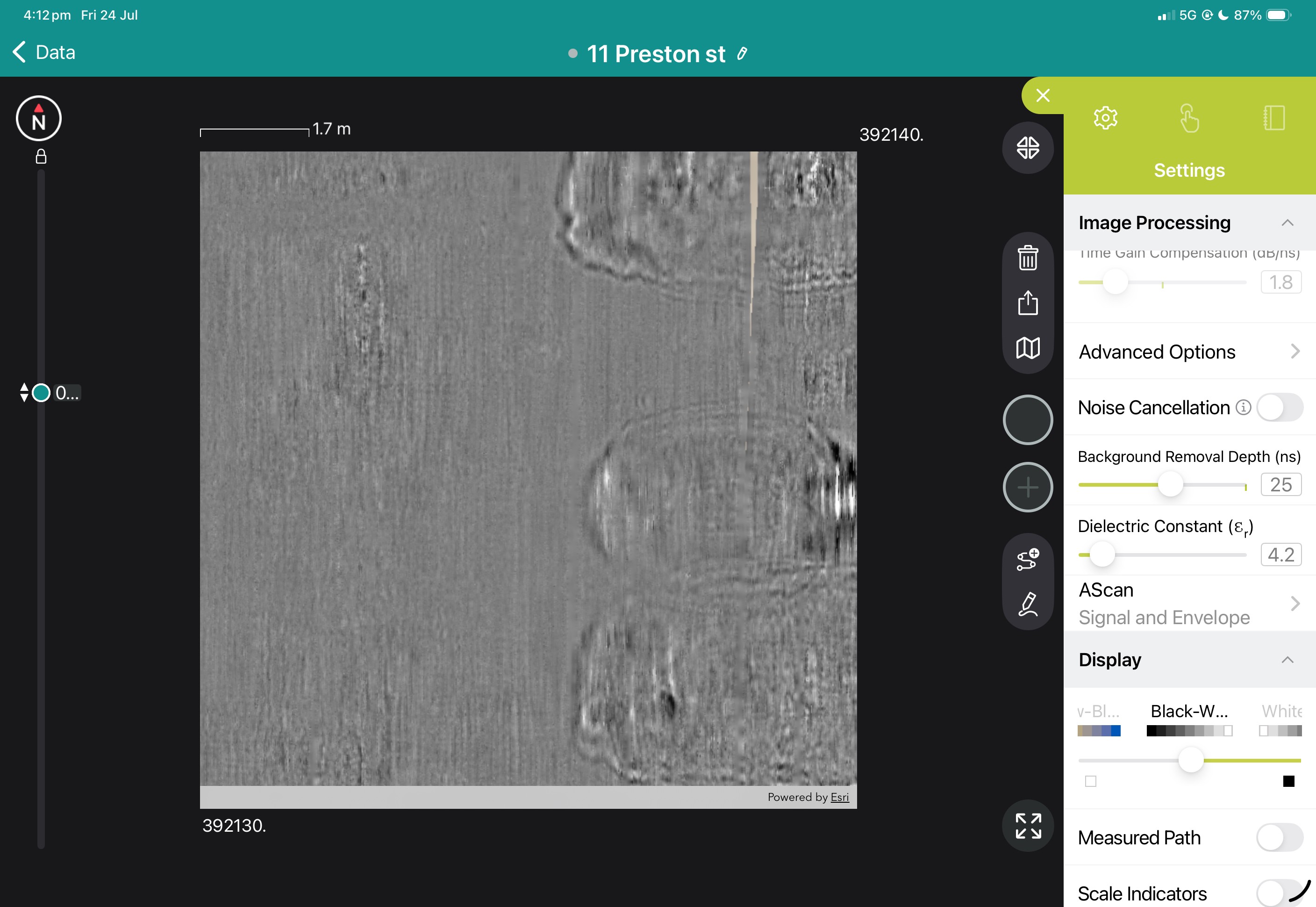
Freepath shown In GPR Insights without Hilbert Transformation
Geotagged linework added to a found sewer
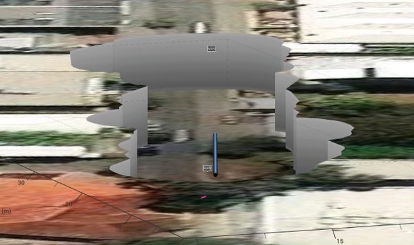
3D view with a cutout showing the sewer
3d Sewer line with GPR data removed
Introdution
The GM8000 Multi-Channel Ground Penetrating Radar system is a high-performance, array-based GPR solution built for rapid, large-area subsurface investigation and infrastructure assessment. Designed to maximise coverage speed, data density, and spatial accuracy, it delivers reliable, high-quality results on projects where efficiency and precision are critical.
By combining multi-channel acquisition with advanced positioning and real-time processing, the GM8000 enables rapid scanning of extensive assets while maintaining consistent data quality. It is selected by engineers, asset owners and consultants who require reliable, scalable GPR workflows for network-level assessment, condition monitoring and digital asset mapping.
Applications
Bridge deck condition assessment and deterioration mapping
Concrete cover measurement and moisture distribution analysis
Asphalt layer thickness evaluation across road networks
Utility mapping including fiber optic and buried services
Detection of subsurface voids and cavities
Large-area infrastructure surveys requiring continuous data capture
Georeferenced subsurface mapping for transport corridors
Archaeological prospection over wide survey areas
Unexploded ordnance (UXO) detection surveys
Features
Hardware and acquisition architecture:
Multi-channel GPR array enables simultaneous data collection across wide swaths, significantly increasing survey productivity.
Modular array configurations support adaptation to different survey types, including bridge inspection and utility mapping.
Integrated positioning using GNSS and visual odometry supports accurate georeferenced data capture.
Data quality and coverage:
High-density data acquisition improves subsurface resolution and continuity across large areas.
Consistent channel spacing supports uniform coverage and reduces gaps typical of single-channel systems.
Real-time processing and filtering improve signal clarity during acquisition, reducing the need for repeat surveys.
Usability and workflow efficiency:
Designed for continuous scanning workflows, enabling efficient coverage of roads, bridge decks and large slabs.
Field calibration tools support reliable setup and repeatable measurements.
Integrated annotation tools allow tagging, voice notes and image capture directly during acquisition.
Immediate generation of CAD and GIS-ready outputs supports faster decision-making and reporting.
GX1 and GX2 Antenna Arrays
The GM8000 system supports interchangeable multi-channel antenna arrays, allowing users to configure the system based on survey requirements, resolution needs and coverage objectives.
GX1 Array:
High-channel-count configuration designed for maximum coverage and productivity over large areas.
Suitable for road, bridge deck and network-level surveys where continuous, high-speed data acquisition is required
Provides dense spatial sampling to support detailed condition mapping and asset-level analysis.
GX2 Array:
More compact multi-channel configuration suited to projects requiring increased manoeuvrability.
Effective for urban environments, confined spaces or targeted investigations where access is constrained.
Balances coverage and flexibility while maintaining multi-channel data quality advantages over single-channel systems.
Operational flexibility:
Array selection enables alignment of system capability with project scope, from high-speed corridor surveys to focused site investigations.
Consistent data structure across arrays supports streamlined processing and interpretation regardless of configuration.
Firmware
The onboard firmware manages synchronized multi-channel acquisition, ensuring consistent timing and alignment across all channels during high-speed surveys. This enables accurate reconstruction of subsurface conditions across wide survey paths.
Real-time signal processing within the firmware supports dynamic gain control, noise reduction and background filtering, improving data clarity during collection. Field calibration functions, including distance and positioning calibration, help maintain measurement accuracy across varying site conditions.
Ongoing firmware updates support enhancements to acquisition stability, processing efficiency and integration with positioning systems, contributing to improved field productivity and data reliability.
Software
The GM8000 is supported by a comprehensive software ecosystem for both field acquisition and advanced post-processing. The system enables immediate visualisation and interpretation of data, while also supporting detailed analysis workflows for engineering and asset management applications.
Visualisation modes include A-scan, B-scan and C-scan, with both migrated and non-migrated views.
Time-slice and geo-referenced mapping views support layer analysis and spatial interpretation.
3D multi-channel data processing enables detailed assessment of subsurface conditions across large areas.
Signal processing tools include gain control, filtering, background removal and noise reduction.
Hyperbola fitting tools assist with target identification and interpretation.
Integration with GNSS data enables mapping over satellite imagery and alignment with survey coordinates.
Export formats include SEG-Y for advanced processing, along with CAD and GIS outputs such as SHP and KML.
Cloud-based workspace supports data storage, collaboration, remote access and project management.
The combined field and office software workflow allows users to move efficiently from acquisition to deliverables, supporting clear communication of results and integration into engineering and asset management systems.
Why the GS9000 matters for SUE businesses
Increase area covered per field day
Reduce the number of manually positioned survey lines
Improve coverage in congested corridors
Review coverage before leaving site
Produce higher-value mapped deliverables
Combine GPR and GNSS in one workflow
Retain raw data for later reinterpretation
Expand from locating into mapping and subsurface modelling
High-resolution multichannel GPR for structures, bridges and pavements
The GX1 transforms the GS9000 into a high-resolution structural assessment system for concrete slabs, bridge decks and pavements. Its dense, dual-polarisation array captures detailed 3D data across wide areas, supporting reinforcement and cover mapping, moisture and deterioration assessment, and analysis of asphalt and pavement layers. Live visualisation helps confirm survey coverage on site, while post-processing tools produce clear, report-ready condition maps.
Bridge-deck reinforcement and condition mapping
Concrete-cover mapping
Reinforcement layout and spacing
Moisture-related and deterioration mapping
Asphalt and pavement-layer thickness
Road and runway investigations
Detection of embedded features
Large-area concrete-slab investigations
Comparative and repeat surveys
The structural assessment workflow
1. Define the inspection area
Import the structure, bridge, pavement or survey background.
2. Collect closely spaced profiles
Capture 35 longitudinal and 15 cross-polarised channels with dense spacing.
3. Review coverage in the field
Use live radargrams and time slices to confirm that the required area has been captured.
4. Process the dataset
Apply velocity, gain, background removal, migration, filtering and topographic correction as appropriate.
5. Generate diagnostic maps
Create depth slices, reinforcement maps, layer information or application-specific condition maps.
6. Integrate with the engineering assessment
Export figures, mapped anomalies and raw data for inclusion in the engineer’s final interpretation and report.
Structural outputs and engineering value
Field information
Live radargrams
Coverage map
Time-slice preview
Field annotations
Processed Diagnostic Information
2D and 3D views
Depth slices
Reinforcement patterns
Cover trends
Layer-thickness information
Comparative amplitude or condition maps
Engineering deliverables
Georeferenced maps
Marked investigation areas
Selected radar profiles
Exported images and datasets
CAD/GIS overlays
Report-ready figures
View some of these features at work below, and our case study if you'd like to see more of what the GS9000 can do.
%20vector%20logo.svg)