Ultrasonic Pulse Velocity Crack Depth Measurement determines the depths of vertical cracks in concrete according to BS 1881 Part 203. The method measures surface velocities in and/or near the crack and use a trigonometric formula to estimate the crack depth. The calculation assumes the crack is open and air filled and vertical.
The BS 1881 method requires the use of an Ultrasonic Pulse Velocity (UPV) system, the only tool that can offer an estimate is a compatible UPV machine such as the Surfer, the Pundit PL 200 or the Pundit Lab. Other sonic or seismic NDT techniques may be influenced by the presence of cracked concrete but they cannot measure the depth of the cracking.
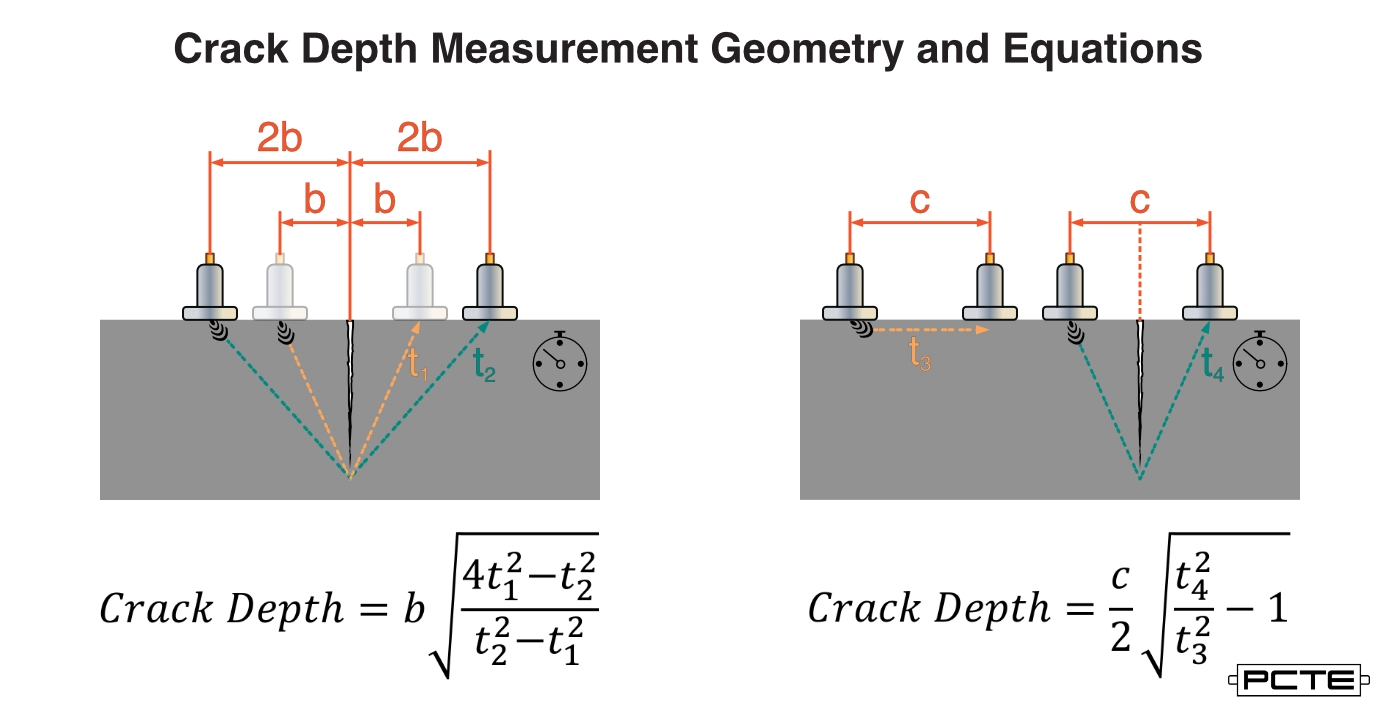
How to Measure Crack Depth in Concrete
To estimate the depth of a surface crack the aim is to arrange two UPV transducers on the concrete surface around the crack, comparing two measurements using an assumed geometry and a trigonometric calculation to determine its depth.
In the image below two possible geometries and the formula used to evalute the Crack Depth are shown.
Crack Depth Measurement Geometry and Equations
The left geometry and calculation matches that used by the Pundit PL and Pundit Lab's built in crack depth estimate modes. The geometry and equation on the right is the same as used by the surfer.
To use either geometry and equation manually.
Mark a line perpendicular to the crack, extending far to the left and right.
To use the left hand equation and geometry
Mark the b/2b measurements on this line
Place the transducers as shown for position b and record the transmission time t1k
Place the transducers as shown for position 2b and record transmission time t2
Calculate crack depth using the left equation
To use the right hand geometry and equation
Mark the measurement c on this line with the crack directly in the middle
Mark a second measurement at spacing c in a region free from cracking
Place the transducers in the un-cracked region at spacing c and record t3
Place the transducers bridging the crack at spacing c and record t4
Calculate the crack depth using the right equation.
Assumptions in UPV Crack Depth
The measurement technique takes advantage of the geometry of the crack and the influence of the crack on sound transmission between the face of two UPV transducers. The Crack Depth Measurement makes the following assumptions;
The crack is oriented perpendicular to the concrete surface, ideally a true 90 degree angle.
The crack is open and air filled, not water filled or tightly pressed together internally.
The fast signal path for sound is a line transmitting through the surface concrete between the face of UPV transducers applied to the surface of un-cracked concrete
When the UPV transducers are placed on either side of a crack the fastest signal path is now from the face of one transducer, to the bottom / toe of the perpendicular crack and then direct from this point to the face of the second UPV transducer.
The concrete in the vicinity of the crack is uniform and homogenous.
If these assumptions hold true the process will produce a reosnable estimate of the crack depth.

%20vector%20logo.svg)


