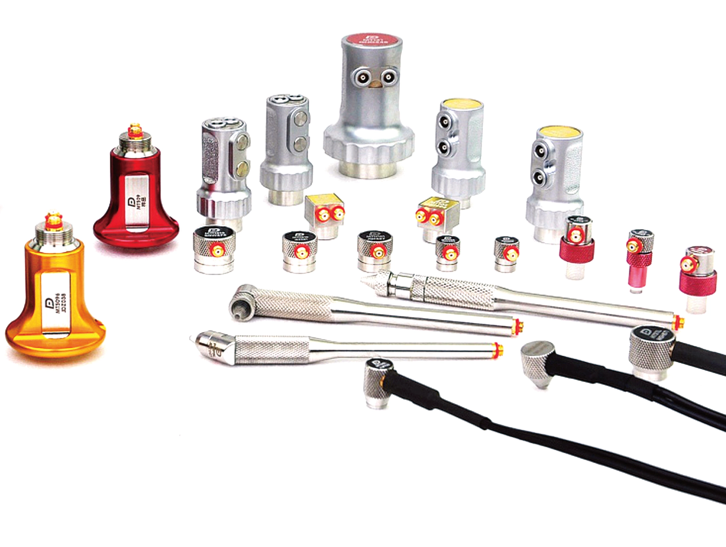
Couplant is used to exclude the air between the surface of the ultrasonic probe to the test component. Couplant is packaged in many sizes and is available as a liquid or in a powder. Contact PCTE's team to special order to your exacting requirements.
$ 0.00 AUD
This product is out of stock.
Product is not available in this quantity.
Thank you! Your submission has been received!
Oops! Something went wrong while submitting the form.
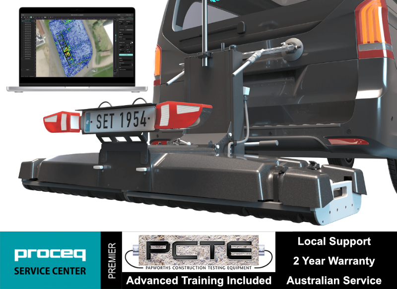
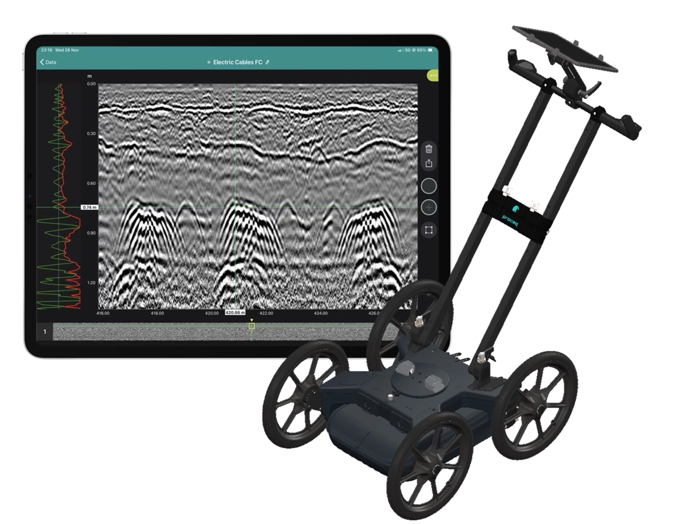
Collect high-density, georeferenced GPR data across wide areas and view the subsurface in 3D as you scan. Choose the GX2 array for SUE and utility mapping, or the GX1 array for structural, bridge and pavement investigations.
Why use the GS9000 instead of a conventional single-channel GPR?
Cover more ground
Collect multiple parallel profiles in one pass instead of uilding a grid line by line.
See results during acquisition
View georeferenced radargrams and time-slice information in the field rather than waiting until the data is returned to the office.
Produce repeatable mapped data
Combine wheel-positioned GPR data with GNSS, project coordinates and survey linework.
Use one platform for two very different applications
Exchange GX1 and GX2 arrays without purchasing two complete cart platforms.
High-density 3D GPR mapping for SUE and utility investigations
The GX2 transforms the GS9000 into a high-density subsurface utility mapping system. Its 11-channel, low-frequency GPR array captures an 83 cm-wide swath in each pass, helping operators detect and map buried pipes, ducts, cables, voids and other subsurface features. Live georeferenced data lets SUE teams review coverage on site and produce accurate CAD, GIS and project-coordinate deliverables.
Utility corridor mapping
Detection of pipes, ducts and cables
Mapping non-conductive services that may not respond to electromagnetic locating
Congested service investigations
Road-crossing and easement surveys
Potential void and cavity investigation
Pre-excavation and design-stage surveys
Utility mapping to project or local coordinates
The SUE field workflow
1. Plan the survey
Load satellite imagery, CAD information, project coordinates or survey control.
2. Collect dense multichannel data
Survey an approximately 0.82 m-wide swath with 11 channels in each pass.
3. Review data live
Examine radargrams, georeferenced time slices and marked features while still on site.
4. Interpret and digitise
Add points, linework, tags, photographs and field observations.
5. Process and deliver
Merge survey areas, apply processing and export mapped information for the customer’s CAD, GIS or reporting workflow.
SUE Outputs and Deliverables
Georeferenced time-slice maps
Radar profiles
Utility alignments and interpreted linework
Depth estimates
Survey trajectory
Points of interest
Field photographs and annotations
CAD, SHP and KML outputs
SEG-Y raw-data export
Project-coordinate and local-grid outputs
PDF or shareable project reports
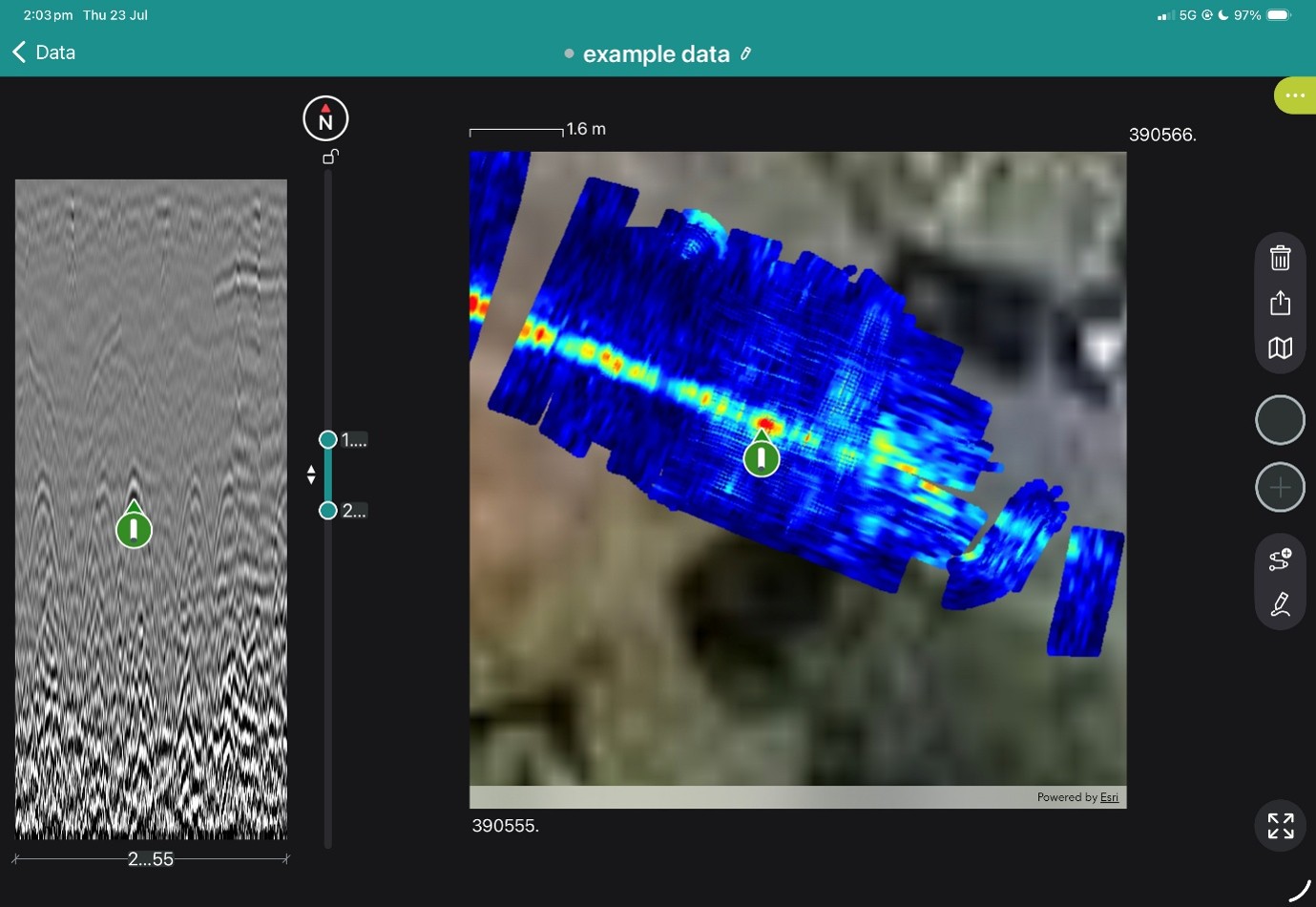
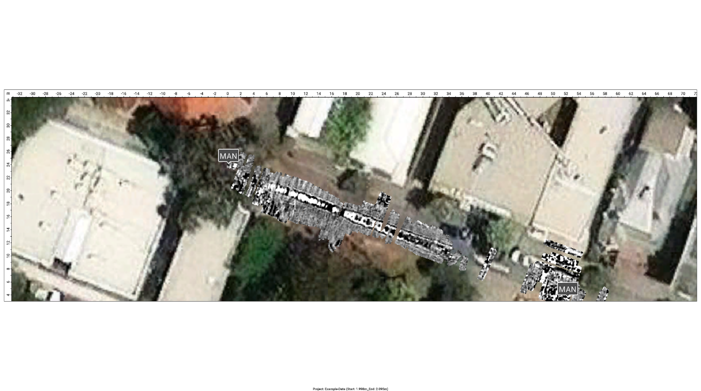
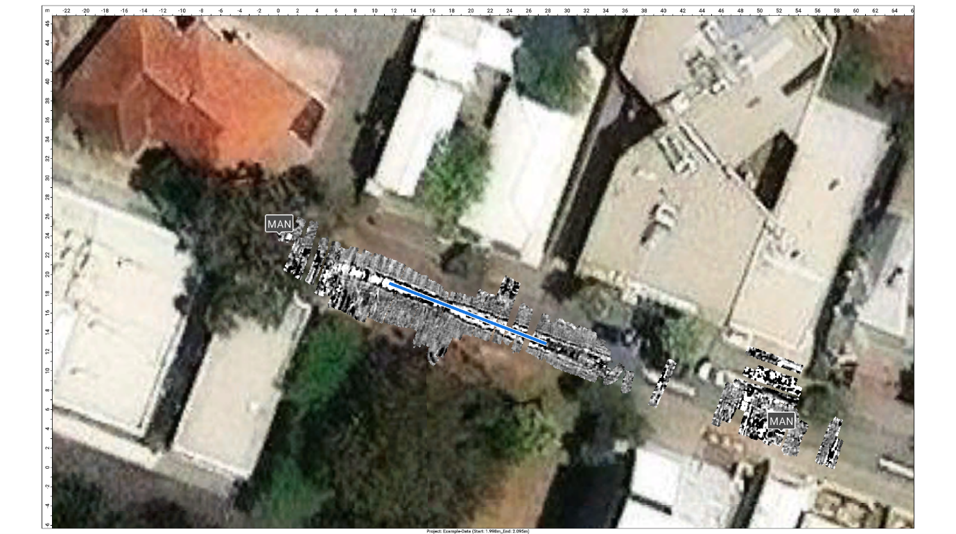
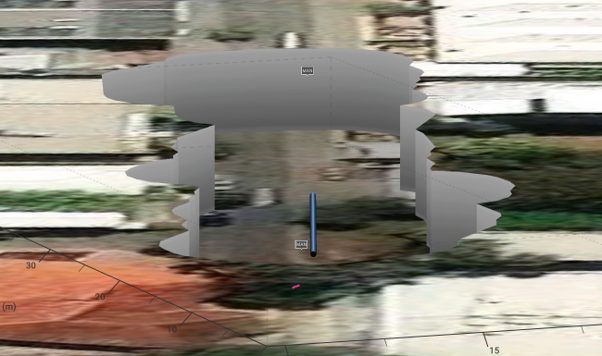
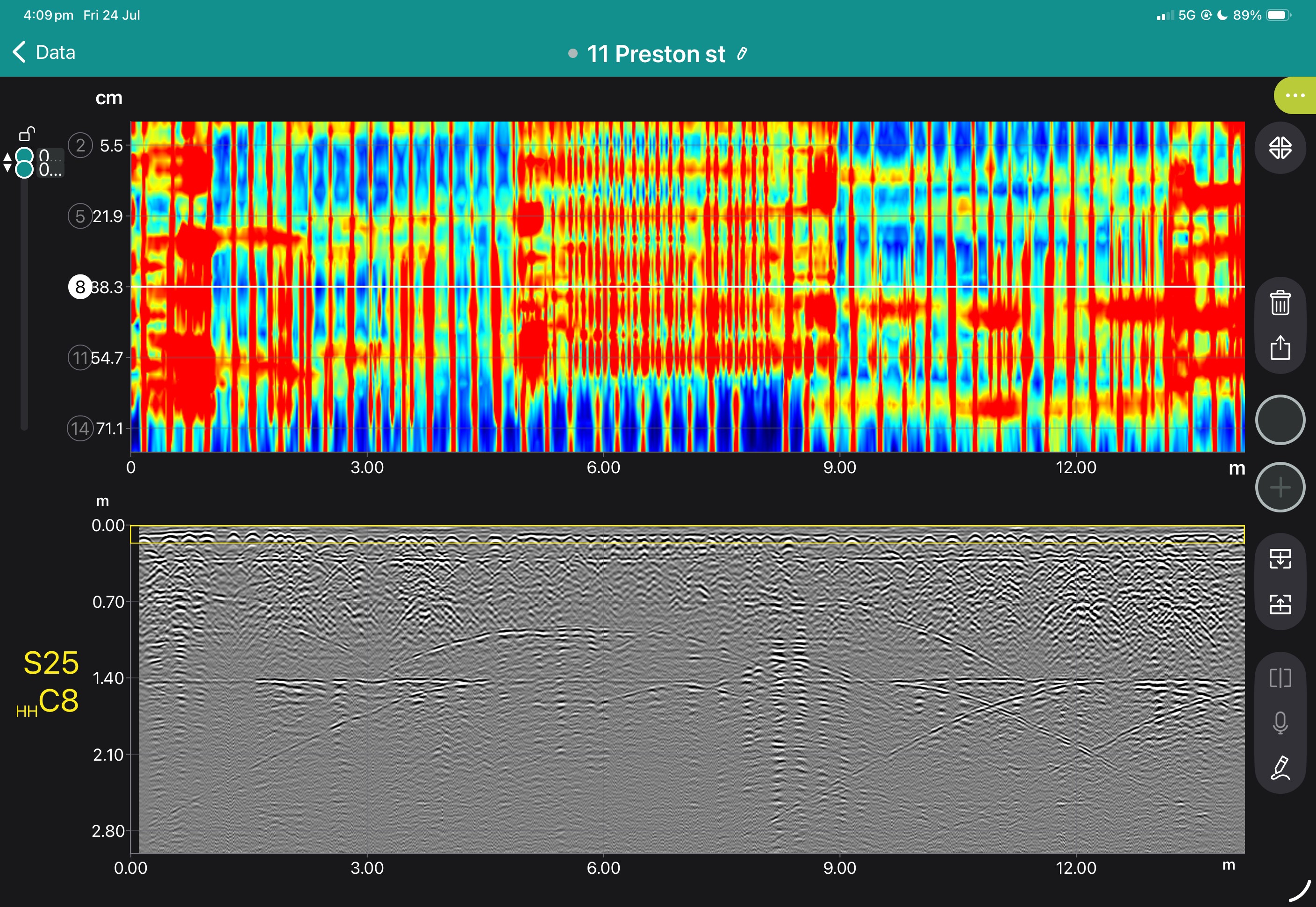
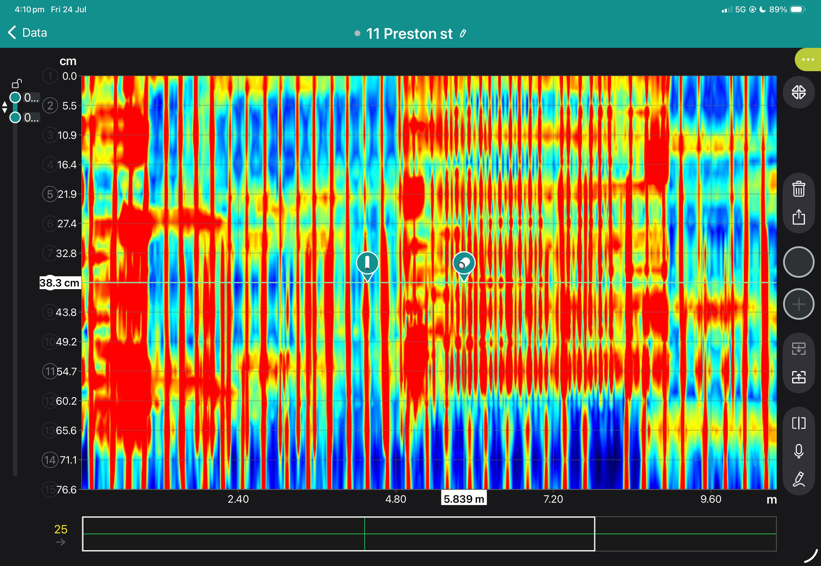
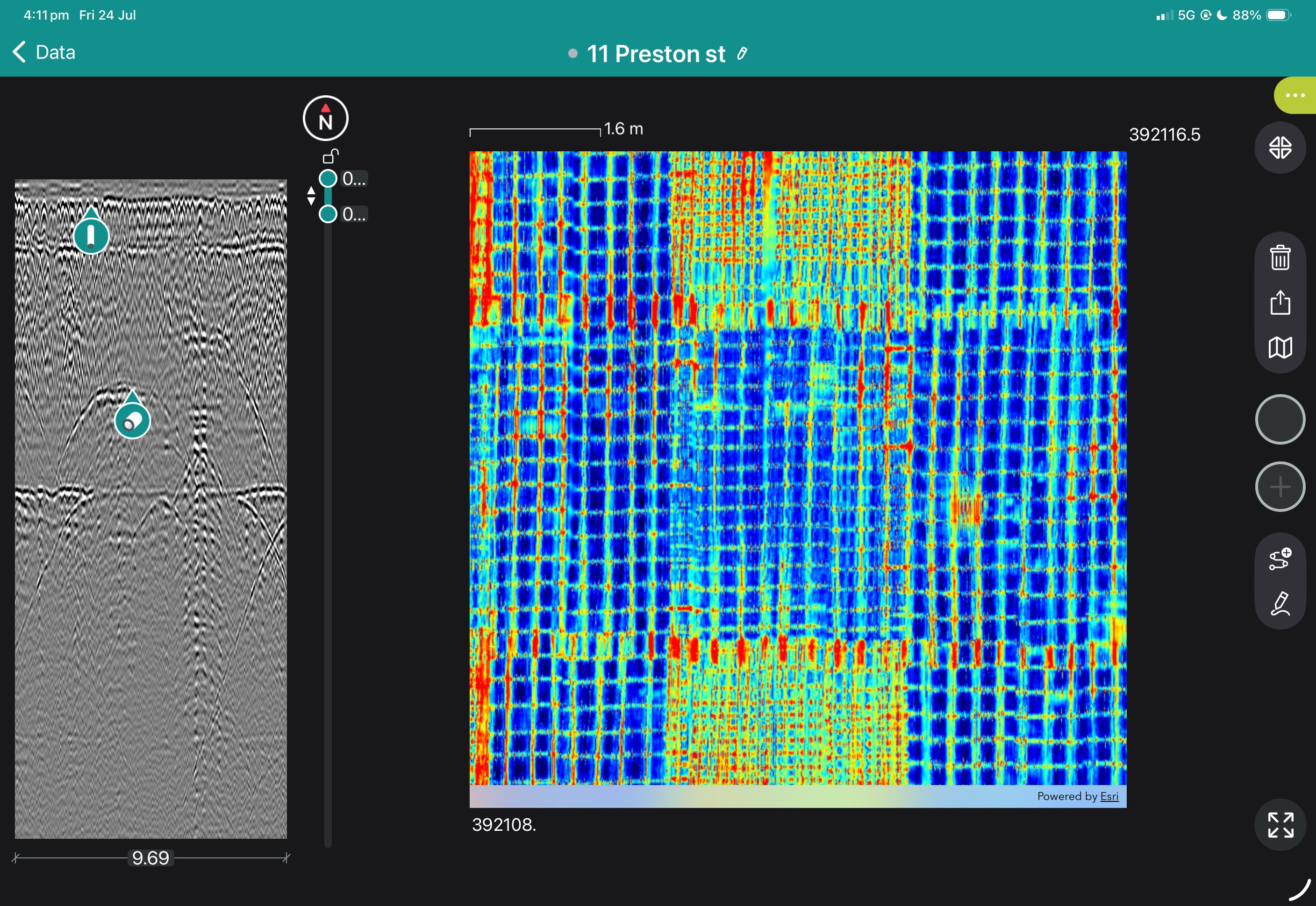
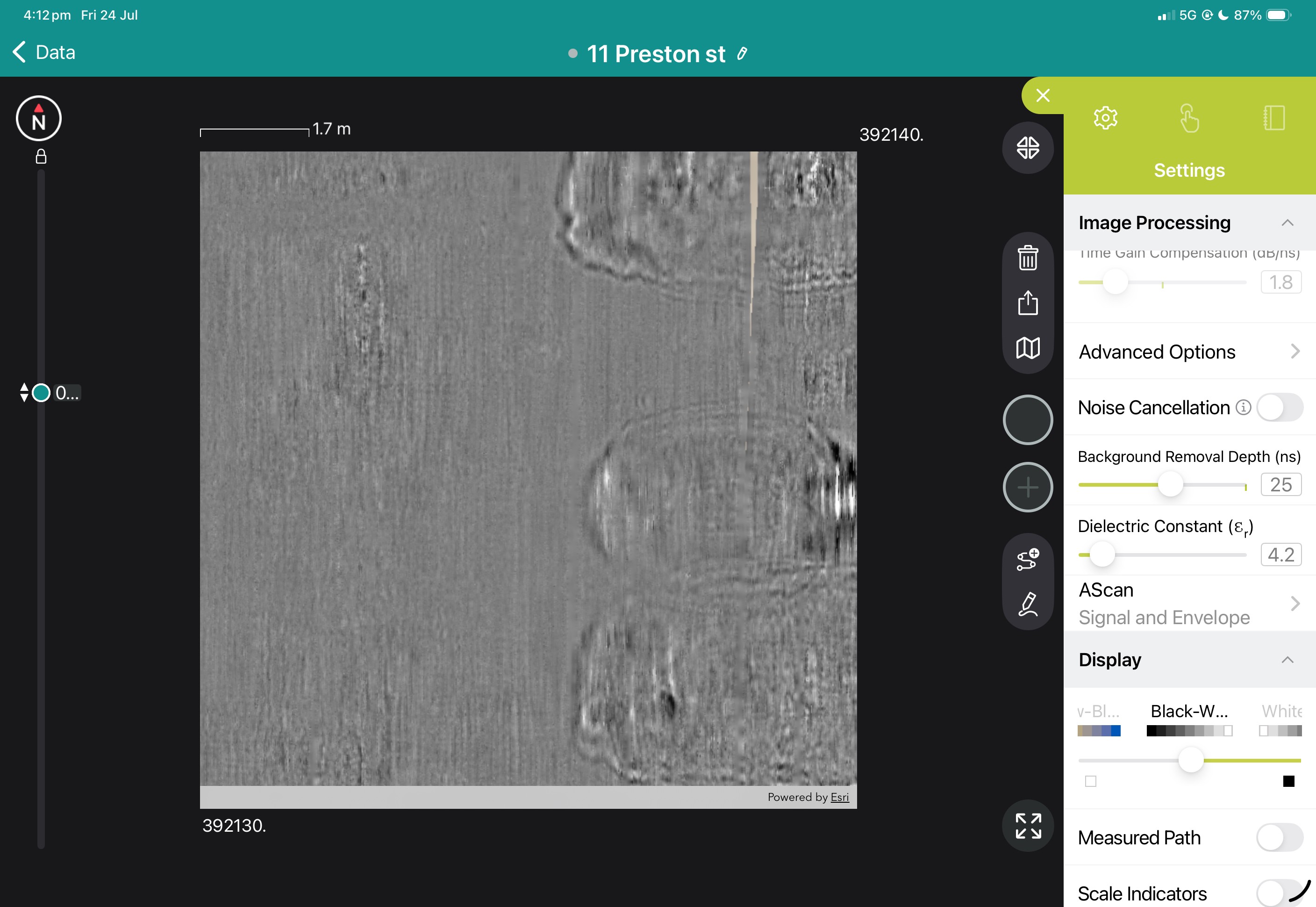
View the images below to see these in action.
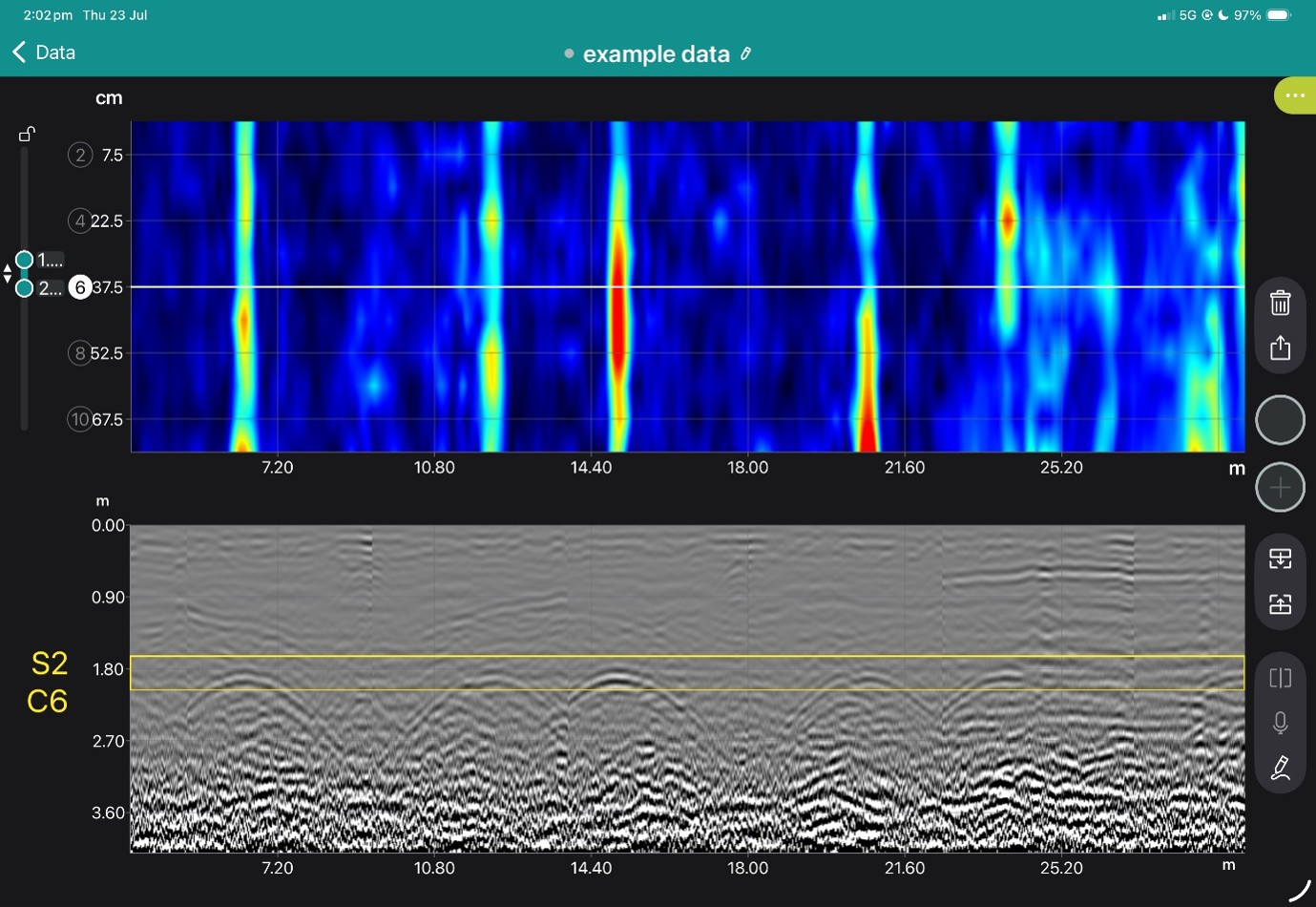
Superline and B Scan from App
Freepath and b-scan from app
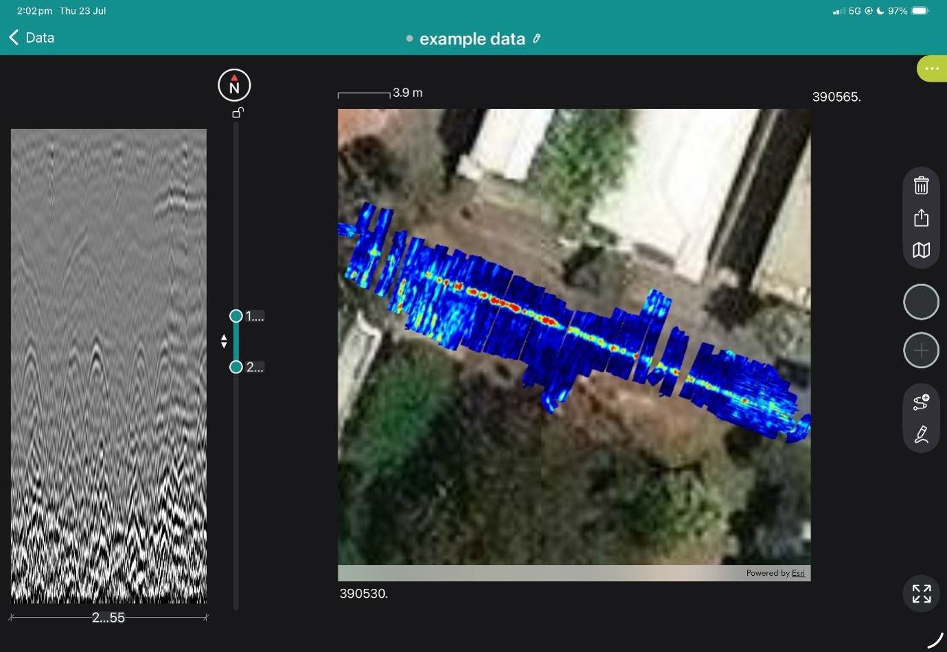
Geolocated tag on freepath in app
Freepath shown In GPR Insights without Hilbert Transformation
Geotagged linework added to a found sewer
3D view with a cutout showing the sewer
3d Sewer line with GPR data removed
SuperSonix Ambient UT Gel
SuperSoniX is an enhanced performance couplant with a broad operating range, slow evaporation rate and gel viscosity that remains in place.
Gel viscosity remains in place for overhead and vertical surfaces
Broad operating range for a water-based couplant
Slow drying
Salt-stable viscosity
Water-soluble
Environmental and operator friendly
Contains glycerin. Not for aluminum aircraft inspections.
UltraSonix
UltraSoniX is a high-performance couplant, available in medium viscosity, ideal for spreading.
-12°C to 104°C temperature range for most flaw detection and thickness gauging applications.
Water-soluble: easy to remove Environment and operator-friendly – no formaldehyde, nitrates, nitrites, or glycol ethers.
Lower residue than most UT couplants.
No glycerin as required for carbon fiber composites.
Removal: Wipe with wet or dry paper or cloth rag or water wash.
EchoMix® Single Powder
Single packet powdered UT couplants provide an economical solution for travel, remote access inspections and storage limitations.
EchoMix Single is a one-part (one packet) powder, easily mixed in ambient water in five minutes, providing a strong, continuous coupling film that adheres well to vertical and overhead surfaces. Single mix packet, one step mixing.
Easiest mixing powder couplant
One packet
Less residue
Blue mixing tracer
Salt stable – will not thin with corrosion salts or in marine or highway environments
Fast, easy removal with water
Compact for shipping and storage
Easy mixing, fast gel time in ambient water
Removal: Remove with a dry rag, water and brush or pressure washer.
Air Bubbles: All powder couplants will form small air bubbles after mixing if water is not de-aired. These small bubbles usually do not negatively affect the use of the couplant and will dissipate in 3-4 days. If an air bubble-free couplant is desired immediately, use hot water and allow to stand overnight; then proceed with adding the powder couplant.
The Blue Color is a visual marker to ensure uniform distribution of the corrosion inhibitor by encouraging thorough mixing.
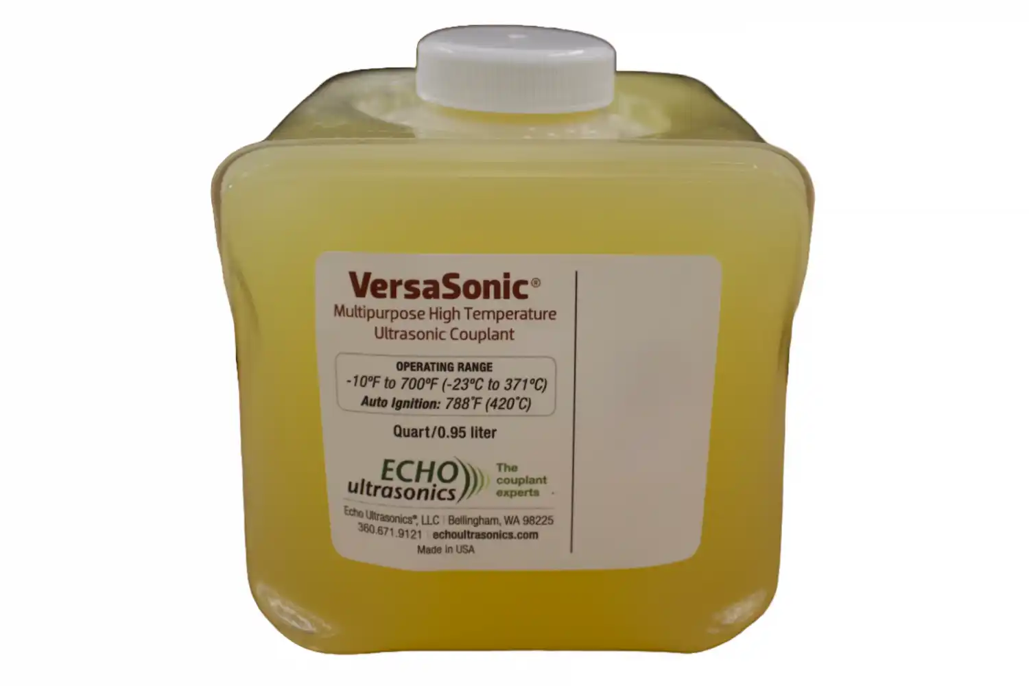
VersaSonic High Temperature Couplant
VersaSonic® is Echo Ultrasonics' most versatile couplant, from high temperature on turbine rotors to extreme weather inspections. VersaSonic is a low-toxicity, biodegradable couplant that does NOT contain peanut oil.
Instantaneous ultrasonic response (does not contain plastic powders which delay ultrasonic conduction)
Excellent high temperature transducer lubricant, extends transducer life
Multiple viscosities covering flaw, corrosion mapping and thickness gauging at high and low temperatures and in mud, snow and rain
Ambient and low temperature coupling where corrosion inhibition is critical
Excellent corrosion inhibitor. Provides non-toxic, superior, long-term corrosion inhibition for steel and cast iron and is compatible with other metals and most plastics. VersaSonic may be left in place unless it will interfere with subsequent manufacturing operations such as painting or electroplating
Low environmental impact. Contains no perfluorocarbons, silicones, peanut or tree nut oils.
Removal: wipe with paper or cloth rag. If complete removal is required, dish detergent and water or a chemical degreaser can be used.
Why the GS9000 matters for SUE businesses
Increase area covered per field day
Reduce the number of manually positioned survey lines
Improve coverage in congested corridors
Review coverage before leaving site
Produce higher-value mapped deliverables
Combine GPR and GNSS in one workflow
Retain raw data for later reinterpretation
Expand from locating into mapping and subsurface modelling
High-resolution multichannel GPR for structures, bridges and pavements
The GX1 transforms the GS9000 into a high-resolution structural assessment system for concrete slabs, bridge decks and pavements. Its dense, dual-polarisation array captures detailed 3D data across wide areas, supporting reinforcement and cover mapping, moisture and deterioration assessment, and analysis of asphalt and pavement layers. Live visualisation helps confirm survey coverage on site, while post-processing tools produce clear, report-ready condition maps.
Bridge-deck reinforcement and condition mapping
Concrete-cover mapping
Reinforcement layout and spacing
Moisture-related and deterioration mapping
Asphalt and pavement-layer thickness
Road and runway investigations
Detection of embedded features
Large-area concrete-slab investigations
Comparative and repeat surveys
The structural assessment workflow
1. Define the inspection area
Import the structure, bridge, pavement or survey background.
2. Collect closely spaced profiles
Capture 35 longitudinal and 15 cross-polarised channels with dense spacing.
3. Review coverage in the field
Use live radargrams and time slices to confirm that the required area has been captured.
4. Process the dataset
Apply velocity, gain, background removal, migration, filtering and topographic correction as appropriate.
5. Generate diagnostic maps
Create depth slices, reinforcement maps, layer information or application-specific condition maps.
6. Integrate with the engineering assessment
Export figures, mapped anomalies and raw data for inclusion in the engineer’s final interpretation and report.
Structural outputs and engineering value
Field information
Live radargrams
Coverage map
Time-slice preview
Field annotations
Processed Diagnostic Information
2D and 3D views
Depth slices
Reinforcement patterns
Cover trends
Layer-thickness information
Comparative amplitude or condition maps
Engineering deliverables
Georeferenced maps
Marked investigation areas
Selected radar profiles
Exported images and datasets
CAD/GIS overlays
Report-ready figures
View some of these features at work below, and our case study if you'd like to see more of what the GS9000 can do.
%20vector%20logo.svg)